Tank Weighing System: Components, Installation, and Selection
Learn how a tank weighing system works, which components it needs, how piping and agitation affect readings, and how to plan installation and calibration.
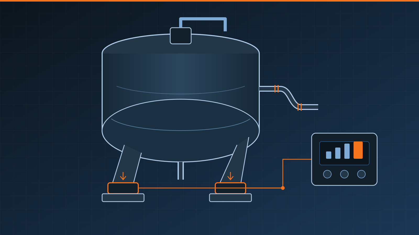
A tank weighing system measures a vessel and its contents by supporting the structure on load cells and converting their combined output into a calibrated weight. A practical system includes correctly selected load cells, engineered mounts, a junction or communications arrangement, and an indicator or controller. Its performance depends as much on the vessel, piping, restraints, environment, and installation as on the sensors.
Key takeaways
- Specify the full operating envelope: vessel dead load, maximum contents, process forces, maintenance loads, and credible upset conditions.
- Engineered mounts transfer vertical load while controlling uplift, lateral movement, and alignment as required by the application.
- Piping, hoses, agitators, wind, and thermal movement can create forces that appear as weight or bypass the sensors.
- Junction boxes and indicators must match the load cells, environment, cable architecture, and control system.
- Calibrate the assembled vessel after installation and verify it under representative process conditions.
- Structural, process, electrical, and metrology specialists should review the design; this article is general guidance.
What makes up a vessel weighing system?
The measurement chain normally contains four functional layers:
| Component | Main purpose | Selection focus |
|---|---|---|
| Load cells | Convert force at the vessel supports into electrical measurements | Capacity, output, environmental suitability, overload conditions, and compatibility |
| Mounting assemblies | Introduce load correctly and manage alignment, lateral forces, uplift, and movement | Vessel support geometry, restraints, thermal travel, stability, and installation clearances |
| Junction or communications system | Combine analog signals or carry individual sensor data to the instrument | Cell count, trimming or diagnostics, enclosure, cabling, and indicator compatibility |
| Indicator or controller | Excite and read sensors or receive their data, calibrate weight, display values, and interface with controls | Resolution, filtering, I/O, protocols, records, control logic, and environment |
This multi-support arrangement differs from the small platforms discussed in our single point load cell guide. Tank design is about distributing a large structure across engineered support points and controlling external forces, not supporting a compact platform on one centrally designed sensor.
Some systems use conventional analog cells connected through a summing box. Others provide separate channels or digital sensor communications. There is no universal wiring, trimming, or diagnostics architecture. Document the entire signal path and use mutually compatible components.
Start with loads and mechanical behavior
Begin with vessel drawings and process data, not a load-cell catalog. Determine the empty vessel weight and every permanently supported item: insulation, jacket contents, platforms, agitator, motor, valves, ladders, and attached equipment. Add the maximum product load plus credible loading during cleaning, maintenance, blockage, filling, or upset conditions. The usable measurement range may be only the changing contents, while the sensors must safely carry the total supported load.
Load rarely divides perfectly between supports. Foundation level, support stiffness, center-of-gravity shifts, piping, and fabrication tolerances can put more force on one cell. Capacity selection therefore needs an engineered assessment of individual support reactions and overload scenarios rather than total weight divided by the number of legs.
Mounting assemblies are not generic brackets. They help apply force through the intended loading axis while accommodating limited installation misalignment or movement defined by their design. Depending on the application, they may also address uplift and lateral loads. Stops, check rods, braces, and anchors must control the vessel without becoming unintended parallel load paths during normal weighing.
Structural stability and measurement accuracy are separate concerns. A qualified engineer should assess the supports, foundation, anchorage, environmental loads, and consequences of a failed support. Never use a load cell as an improvised restraint.
Piping, hoses, and connected services
Every connection between the live vessel and fixed plant can introduce force. Rigid product pipes, jacket lines, vents, electrical conduit, pneumatic tubing, dust extraction, flexible hoses, and cable bundles may support part of the vessel or pull on it. If that force varies with pressure, temperature, fill level, or maintenance position, the displayed weight can drift even when actual contents do not.
Good mechanical design reduces and stabilizes these interactions. Flexible sections, suitable routing, aligned connections, and properly located supports may help, but flexibility is directional. A connector that accommodates vertical movement may still apply lateral force or pressure thrust. Process integrity and containment cannot be compromised merely to improve weighing.
Agitation and product movement
An agitator adds motor torque, vibration, and dynamic forces. Sloshing, aeration, recirculation, filling impact, and uneven solids can continuously redistribute load among tank load cells. These effects do not necessarily mean the sensors are faulty.
Define whether the process needs an instantaneous dynamic estimate, a stable weight after settling, or a controlled cutoff during filling. Indicator filtering can make a display easier to read, but excessive filtering delays response and can cause a controller to overshoot a target. PLC or terminal logic should identify stale, unstable, or invalid measurements rather than treating every number as settled mass.
Where practical, establish a repeatable operating condition for inventory readings—for example, specified valve states and agitator status—then test whether it reflects the production need. Do not stop essential mixing or alter a safe process solely to obtain a quieter display without process and safety approval.
Wind and thermal effects
Outdoor vessels present a large surface to wind. Wind can shift support reactions, move flexible structures, and act through attached pipework. Restraints and signal processing should be designed for the site and measurement objective; filtering cannot correct an unsafe or mechanically binding installation.
Temperature affects the vessel, supports, piping, sensors, and electronics. Expansion can push against restraints or rigid connections, while solar or process heating may affect supports differently. Select components for the environment, accommodate movement intentionally, and verify relevant operating states.
Condensation, washdown, chemicals, flooding, and cable damage are additional risks. Enclosure ratings only remain meaningful with suitable glands, seals, drain paths, mounting, and maintenance. Provide accessible, protected cable routes and a serviceable location for the load cell junction box.
Installation and commissioning sequence
- Inspect the structure and foundation. Confirm dimensions, level, stiffness, supports, anchor locations, and installation access against the approved design.
- Install mounts without forcing alignment. Follow the mount and cell instructions for orientation, hardware, clearances, tightening, and any temporary lifting or dummy supports.
- Control hazards. Isolate process and electrical energy, stabilize the vessel, and use qualified lifting and rigging procedures before working at supports.
- Complete piping and services. Check that final connections, insulation, platforms, and restraints match the designed live/dead boundaries.
- Protect measurement wiring. Route, shield, ground, seal, and identify cables according to system documentation; do not infer conductors from color alone.
- Inspect individual support response. Verify plausible, consistent sensor outputs before summing and calibration. Investigate binding or an abnormal support rather than hiding it with adjustment.
- Configure and calibrate. Record parameters, zero the completed dead load as appropriate, apply known reference loads, and verify indication and outputs.
- Test the process. Exercise filling, discharge, agitation, valves, communications, alarms, power recovery, and expected environmental states.
Calibrating before permanent piping, insulation, or attached equipment is complete can establish a zero that no longer represents the finished system.
Calibration options and limitations
Calibration establishes the relationship between the installed signal and known load. Methods may include applying traceable test loads, adding known material, using a transfer method, or another procedure accepted for the application. The suitable approach depends on vessel access, capacity, required uncertainty, safety, and regulatory obligations.
A theoretical calibration based only on sensor output and capacity can support setup or diagnostics, but it may not reveal piping forces, load-sharing errors, mechanical binding, or installation effects. When feasible, applied-load verification tests the assembled system more directly. Keep as-found and as-left results, reference equipment details, environmental and process state, configuration, adjustments, and acceptance criteria. Our guide to scale calibration certificates explains what useful service documentation should contain.
For inventory, formulation, custody transfer, or sale by weight, required accuracy and legal controls differ. Consult qualified calibration providers and the relevant authority or standards for the intended use and jurisdiction. No generic calibration interval or tolerance is appropriate for every tank.
Selection checklist
- Vessel geometry, support count, dead load, product range, center-of-gravity changes, and individual reactions
- Filling impact, agitation, pressure effects, maintenance, overload, uplift, lateral load, and stability cases
- Mount movement, restraint strategy, foundation, corrosion protection, and installation clearances
- Piping, hoses, jacket services, vents, conduit, platforms, and other force paths
- Temperature range, gradients, wind, vibration, washdown, chemicals, condensation, and hazardous area needs
- Load-cell electrical characteristics, junction architecture, cable lengths, indicator, I/O, and protocols
- Required display increment, process accuracy, response time, filtering, alarms, and batch or inventory logic
- Safe access for installation, calibration, inspection, lifting, and replacement
- Calibration method, reference loads, records, verification frequency, and regulatory requirements
- Spare parts, diagnostics, drawings, configuration backups, training, and qualified service support
A successful hopper weighing system or tank installation is designed as one mechanical and measurement system. Select components only after documenting load cases and process connections, then commission the finished vessel in realistic states. That approach produces more dependable weight data and makes future drift easier to separate into process, mechanical, electrical, and calibration causes.
Frequently asked questions
How does a tank weighing system work?
Load cells installed at the tank or vessel supports convert the supported force into electrical signals. A junction or summing arrangement combines or communicates those signals, and an indicator converts the result into calibrated weight for display, inventory, batching, or control.
How many load cells does a tank need?
It depends on the vessel geometry, support arrangement, load distribution, capacity, stability, and chosen mounting system. Many vessels use one measurement point at each support, but the design should be engineered as a complete structure rather than selected by a general rule.
Why does a tank weight reading change when an agitator runs?
Agitation can create vibration, torque, fluid movement, and changing forces at the supports. The signal filtering and control logic may need to distinguish process motion from a settled weight, while the structure, mounts, piping, and restraints must avoid unintended load paths.
Can tank load cells measure the contents accurately with connected piping?
They can when piping and services are designed to minimize variable external forces and the complete installed system is calibrated under representative conditions. Rigid or thermally moving connections can bypass or add force to the load cells and cause repeatability or zero errors.
Related guides
In-Motion Weighing: Systems, Accuracy, and Selection
Learn how in-motion weighing works, compare low- and high-speed WIM systems, understand accuracy factors, and select equipment for screening or enforcement.
Conveyor Belt Scales: How Belt Weighing Works
How conveyor belt scales weigh bulk material in motion, the parts involved, what affects accuracy, and where continuous belt weighing is used in industry.
Scale Calibration Frequency: How to Set the Right Interval
Learn how often to calibrate a scale using a risk-based interval based on use, impact, drift, environment, regulations and documented performance history.