Weigh Feeder Types, Operation, and Selection
Learn how a weigh feeder measures and controls material flow, compare belt, screw, vibratory, and loss-in-weight designs, and build a selection checklist.
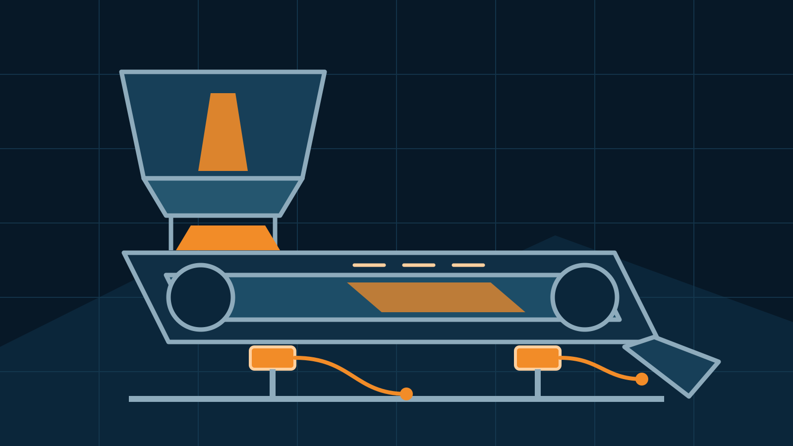
A weigh feeder measures material flow and actively regulates the equipment delivering it. Depending on the design, it may combine a weighed belt, screw, vibratory tray, or suspended hopper with a controller that compares actual mass flow with a target and changes speed or output. Selection should begin with the material, required feed range, process layout, control objective, and safety constraints—not a universal accuracy or tuning claim.
Key takeaways
- A weigh feeder closes the loop between gravimetric measurement and material delivery.
- Belt, screw, vibratory, and loss-in-weight arrangements suit different materials and feed ranges.
- Reliable performance requires stable material presentation, a controlled load path, representative calibration, and suitable control integration.
- Turndown, refill behavior, bulk-density changes, buildup, and process disturbances belong in the specification.
- No controller settings, calibration tolerance, or process-safety measure is appropriate for every installation.
How a weigh feeder works
A controller receives a weight-related signal from one or more load cells. In a belt weigh feeder, it also receives belt speed and calculates mass flow from belt loading and speed. In a loss-in-weight system, it tracks the change in supported hopper mass over time. The controller compares measured flow with the setpoint, then adjusts a motor, belt, screw, gate, or vibration drive to reduce the error.
This feedback loop distinguishes a gravimetric feeder from a purely volumetric device. A volumetric screw running at a given speed assumes that each revolution moves a predictable volume and that bulk density is sufficiently stable. A gravimetric system observes mass delivery, so it can compensate for some density or fill variations. It cannot, however, correct every problem. Bridging, flooding, refill disturbances, mechanical binding, or an unsuitable measurement range can still produce poor control.
A feeder also differs from a conveyor belt scale. The belt scale generally measures material already being conveyed and totalizes throughput. A dedicated belt weigh feeder creates a controlled material bed and varies delivery to meet a commanded rate.
Common weigh feeder types
| Type | How flow is measured and controlled | Often considered for | Important review points |
|---|---|---|---|
| Belt weigh feeder | Measures load on a defined belt section and combines it with belt speed | Free-flowing bulk solids, continuous process feed | Material bed, belt tracking, loading consistency, buildup, tension, speed sensing |
| Weigh screw feeder | Weighs a screw or supported feeder section while screw speed controls delivery | Powders or enclosed transfer where a belt is impractical | Screw fill, inlet pressure, seals, buildup, shaft forces, mechanical isolation |
| Vibratory weigh feeder | Measures supported material or flow while vibration controls transport | Fragile products or materials suited to controlled vibration | Product response, tray dynamics, isolation, amplitude control, environmental vibration |
| Loss-in-weight feeder | Calculates flow from the rate at which a weighed hopper loses mass | Dosing powders, pellets, liquids, or ingredients from a supply vessel | Refill strategy, hopper capacity, isolation, agitation, discharge device, low-level behavior |
These labels describe general architectures, not guaranteed performance. Vendors may combine principles or use different terminology, so compare the actual force path, calculation, operating modes, and test method.
Loss-in-weight feeder as a weigh feeder variant
A loss-in-weight feeder is one important type of weigh feeder, not a separate measurement concept that should be selected in isolation. Its hopper, discharge device, and often a portion of the drive are supported on load cells. The controller estimates feed rate from mass loss over a defined time interval and adjusts discharge output.
During refill, incoming material increases hopper weight and interrupts the normal loss calculation. The system may temporarily hold a recent control output, apply a modeled correction, or use another manufacturer-defined strategy. Refill frequency, refill rate, head pressure, hopper level, and material deaeration can therefore affect delivery. The proposal should state how performance is evaluated during both steady discharge and refill transitions.
Loss-in-weight operation can provide compact, enclosed gravimetric dosing, but nearby pipework, flexible connections, cable tension, dust extraction, or rigid guards can bypass the load cells. The broader load-path principles described for a tank weighing system apply here at a smaller and more dynamic scale.
Material and process questions to define
Begin with representative material data rather than a catalog capacity alone. Record bulk-density range, particle size and shape, moisture, cohesiveness, aeration, temperature, abrasiveness, friability, corrosiveness, and dust behavior. Identify whether the product tends to bridge, rat-hole, flood, smear, compact, or segregate.
Then define minimum, normal, and maximum mass flow; expected turndown; batch or continuous operation; required start and stop behavior; upstream refill conditions; downstream pressure; and allowable product retention. A feeder sized only for maximum rate may have inadequate signal or poor mechanical control at minimum rate. Conversely, a small feeder may run near its mechanical limit and lack reserve for short process demands.
For regulated, hygienic, hazardous, or contamination-sensitive service, specify the applicable site and jurisdictional requirements. Materials of construction, seals, access, cleaning method, dust containment, electrical classification, guarding, and documentation must suit the actual product and facility.
Weigh feeder selection checklist
- Material behavior tested or documented across expected suppliers, moisture, and density
- Minimum, normal, maximum, startup, shutdown, and temporary feed rates
- Required turndown, response time, batch size, totalization, and control objective
- Feeder type, inlet arrangement, discharge geometry, and upstream head conditions
- Load-cell capacity, mechanical isolation, overload protection, and service access
- Belt, screw, tray, gate, agitator, or refill equipment suited to the product
- Temperature, vibration, dust, washdown, corrosion, and hazardous-area conditions
- Controller I/O, communications, setpoint handling, recipes, alarms, and data records
- Calibration and performance test using defined material and operating states
- Safe isolation, guarding, dust control, cleaning, maintenance, and recovery from faults
Installation, calibration, and control
Foundation and support stiffness matter because movement or vibration can enter the weight signal. Install the feeder without forcing inlet or outlet connections into alignment. Flexible connections may reduce transferred force, but they can still pull, stiffen, clog, or apply pressure-related loads. Cables, conduits, covers, and dust boots should not create a parallel load path.
Commissioning should verify mechanical freedom, load-cell signals, zero behavior, speed feedback, motor direction, material presentation, alarms, and communications before closed-loop production trials. Calibration may involve certified test loads, weighed material trials, or another documented method appropriate to the equipment and intended use. Compare delivered material with the reference over representative rates and operating modes, including refill where relevant.
Controller gain, filtering, sampling, and correction limits affect stability and response. Aggressive tuning can hunt or amplify disturbances; heavy filtering can delay correction. There is no safe universal setting. Use the equipment manufacturer’s procedure and tune with qualified controls and process personnel under controlled conditions.
Safety and ongoing verification
Feeders contain moving belts, screws, shafts, pinch points, stored material, electrical energy, and sometimes combustible dust or hazardous product. Guard moving parts, provide suitable isolation and lockout, control unexpected startup, and assess dust, pressure, temperature, and process hazards. Never enter, clear, or service a feeder based on a generic article.
Inspect for buildup, belt tracking, worn flights, loose mounts, damaged cables, blocked flexible connections, and changing material presentation. Trend zero, reference checks, control error, and delivered-mass tests so gradual degradation is found before production is affected.
This is general selection guidance, not a process-safety design, tuning procedure, or universal calibration standard. Follow manufacturer instructions and the site’s engineering, quality, safety, and regulatory requirements. Qualified weighing, controls, mechanical, and process specialists should define acceptance criteria and approve commissioning for the actual installation.
Frequently asked questions
What does a weigh feeder do?
A weigh feeder continuously measures material passing through or leaving a controlled section and adjusts its feed mechanism to maintain a target mass flow. Its controller uses the weight signal and, where applicable, speed or displacement data to calculate and regulate delivery.
What is the difference between a weigh feeder and a conveyor belt scale?
A weigh feeder both measures and controls feed rate, usually through a dedicated short belt or another metering device. A conveyor belt scale primarily measures and totalizes material already moving on a conveyor, although its signal may be used by a separate control system.
Is a loss-in-weight feeder a type of weigh feeder?
Yes. A loss-in-weight feeder is a gravimetric variant that calculates discharge rate from the reduction in hopper weight over time. It is useful for controlled dosing, but refill behavior, material characteristics, mechanical isolation, and the required feed range must be considered.
How accurate is a weigh feeder?
There is no universal accuracy figure. Installed performance depends on feeder design, material behavior, flow range, loading, speed measurement, mechanical installation, environment, calibration method, control tuning, and the definition of the test.
Related guides
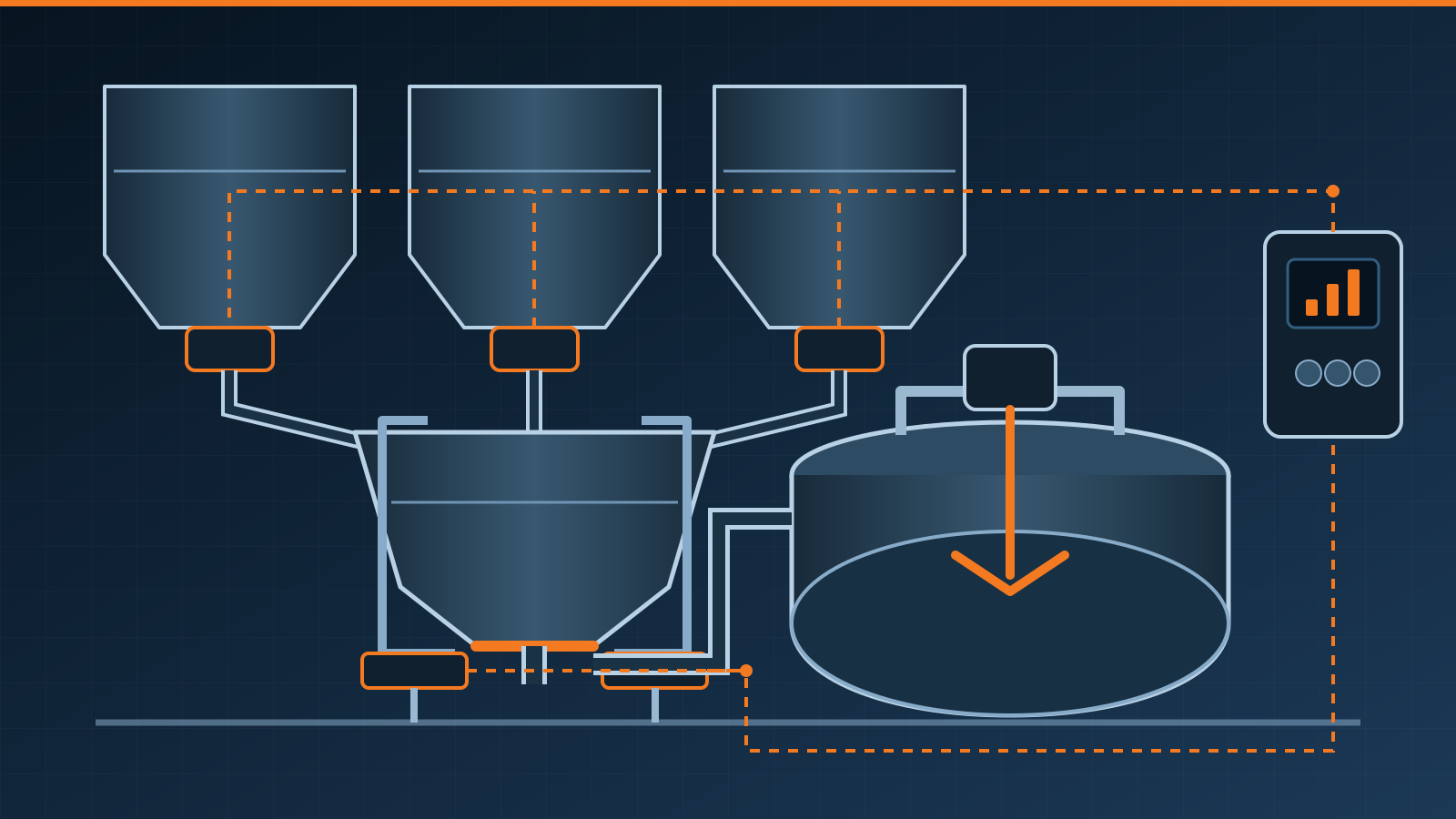
Batch Weighing System: Process, Design, and Selection
Learn how a batch weighing system works, compare gain- and loss-in-weight architectures, and plan safe, dependable material and controls integration needs.
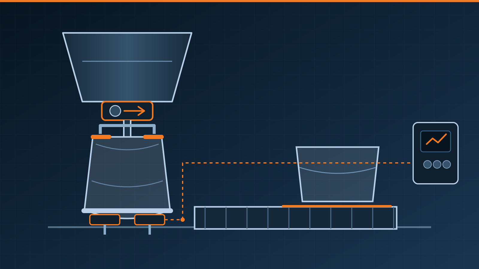
Bagging Scale: Selection and Integration Guide
Learn how a bagging scale weighs and fills bags, how major system types differ, and what to specify for safe, reliable packaging-line integration needs.
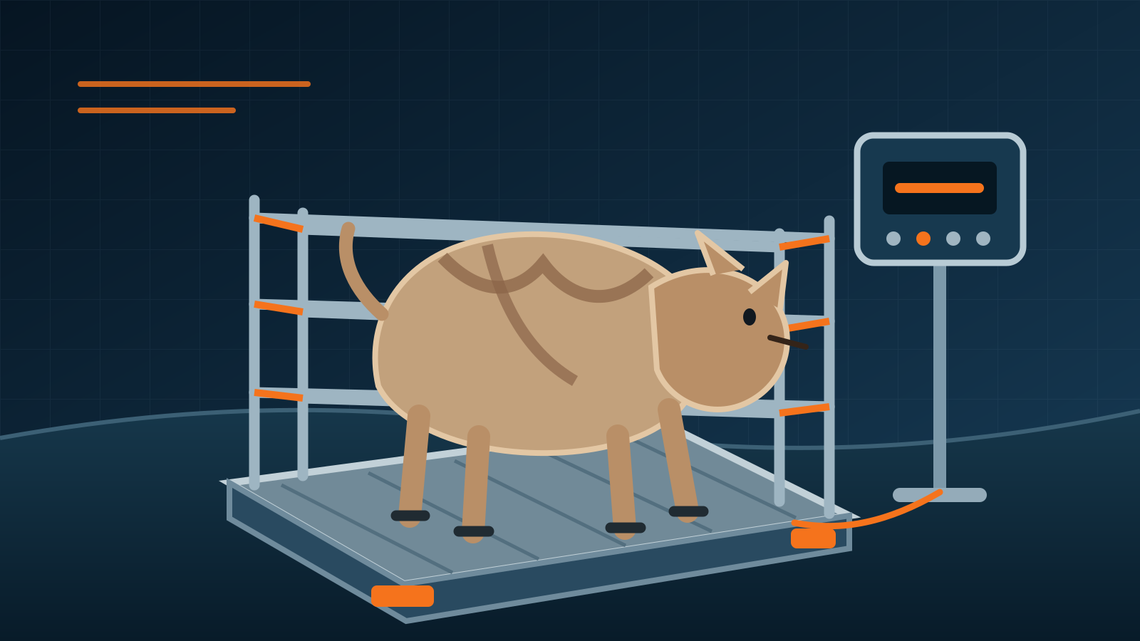
Livestock Scale Guide: Types, Handling and Selection
Learn how livestock scales work, compare platform, alley, crate and portable designs, and plan safer animal handling, installation, weighing and maintenance.