Load Cell Junction Boxes: Summing, Wiring and Corner Adjustment
Learn how a load cell junction box sums signals, supports corner adjustment, protects wiring, and what to check when selecting or troubleshooting one.
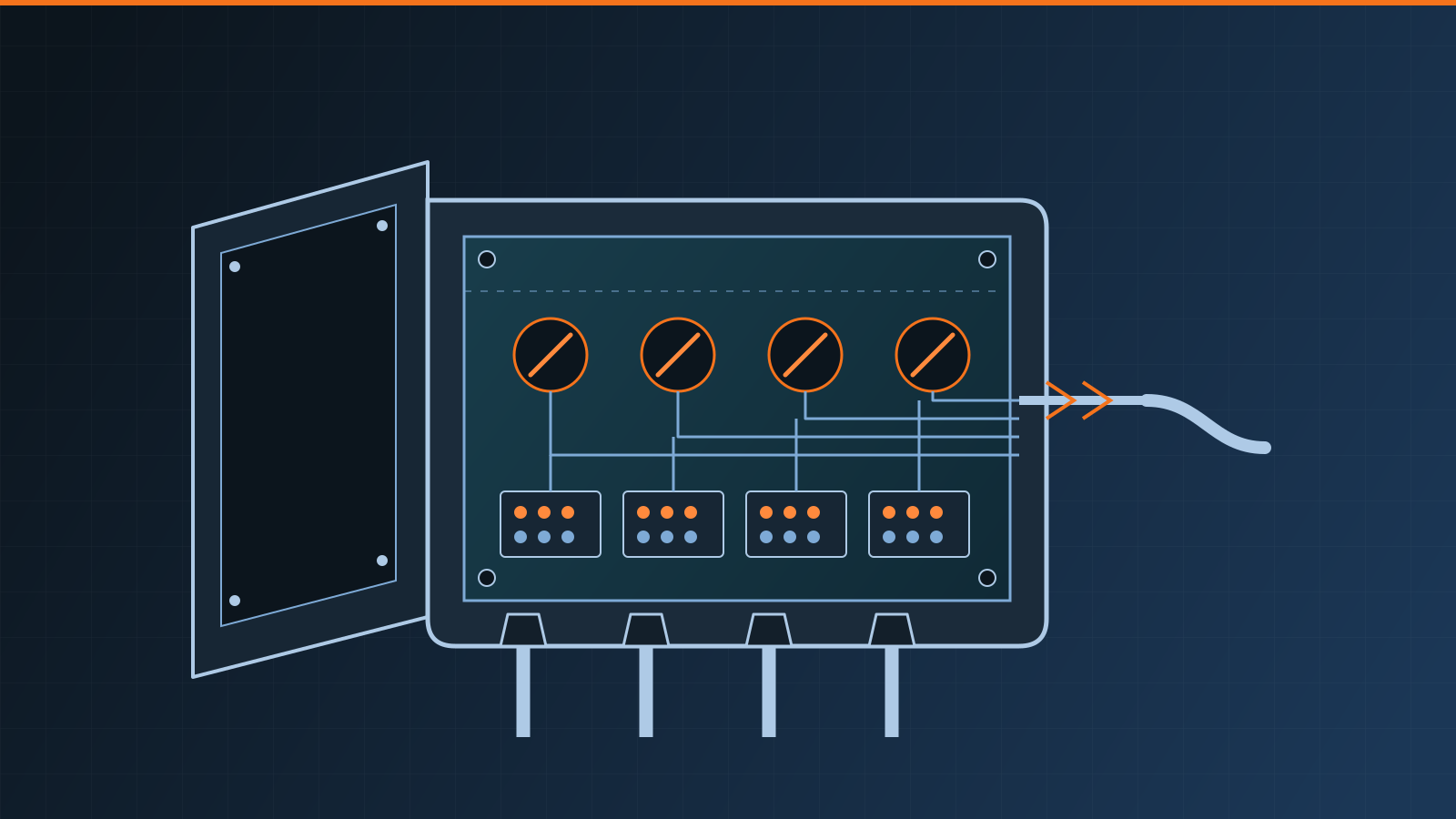
A load cell junction box is the protected connection point that combines the analog outputs of several load cells into one signal for a weighing indicator. Often called a load cell summing box, it also may provide corner-adjustment controls that balance small output differences between cells. It does not replace the indicator, and it cannot compensate for a mechanically defective scale.
Key takeaways
- A junction box sums multiple load cell signals and sends the combined output to the indicator.
- Trim controls support corner adjustment, but only after mechanical faults have been ruled out.
- Moisture, corrosion, loose terminals, cable damage and poor shielding can cause drift or unstable readings.
- Wiring colors and terminal layouts are not universal; use the cell, box and indicator documentation.
- Selection must account for electrical compatibility, cell count, environment, access and serviceability.
- Wiring, measurement and calibration should be handled by a qualified scale technician under safe site procedures.
How summing works in a multi-cell scale
A platform, hopper or vehicle scale may use one load cell at each support point. Each strain-gauge cell is an electrical bridge that receives excitation from the indicator and returns a small signal proportional to its share of the applied load. The junction box connects those circuits so the indicator receives a combined output representing the total load.
In a conventional analog arrangement, the box provides terminals for excitation, signal and any additional conductors required by the system. A home-run cable then carries the combined circuit to the indicator. Some systems use different architectures, including individually monitored sensors or digital communications, so “junction box” does not always mean a passive analog summing circuit.
This role is distinct from the sensing principle described in our overview of how strain-gauge load cells work. The cells create the measurement signals; the summing box brings them together.
Junction box versus weighing indicator
Confusing these components can lead to the wrong replacement or test plan.
| Component | Main job | What it normally does not do |
|---|---|---|
| Load cell | Converts applied force into an electrical output | Display a calibrated weight |
| Junction or summing box | Connects, protects and combines several cell circuits; may provide trim adjustment | Independently calculate and display weight |
| Weighing indicator | Supplies excitation, reads the combined signal, applies calibration and displays or transmits the result | Correct structural binding or protect field splices by itself |
A fault at any one of these layers can affect the display. Replacing the indicator will not dry a wet junction box, and trimming the box will not straighten a damaged mount.
What corner adjustment does
When a known load is placed over different support points, small differences in cell output or load distribution can produce different readings. Corner adjustment—also called corner balancing or trimming—uses the junction box controls to bring those positions into agreement within the requirements of the specific scale.
Depending on the design, trimming changes the contribution of an individual load cell or channel to the summed signal. The adjustment method and sequence vary. There is no universal control direction, terminal arrangement or number of adjustment passes.
Mechanical condition comes first. Before adjusting, a qualified technician should confirm that the deck or vessel moves as intended, mounts are correctly aligned, restraints are not binding, debris is not bridging the structure, and the load can be applied safely at the required positions. A large corner error may indicate a damaged load cell, cable fault, poor support or structural problem. Using trim to hide that defect can reduce useful adjustment range and leave the underlying failure in service.
After component replacement, wiring work or corner adjustment, the complete instrument normally needs calibration and appropriate verification. The principles of documented as-found and as-left performance are covered in our guide to scale calibration certificates.
Load cell junction box wiring: why documentation matters
A technician may encounter conductors for positive and negative excitation, positive and negative signal, sense circuits, shield or drain, and protective grounding. The exact arrangement depends on the cells, indicator, cable and junction box.
Do not connect by color alone. Color conventions differ between products, and a previously repaired cable may not retain the expected conductors. Likewise, a shield terminal is not interchangeable with a signal return or protective-earth point. Incorrect connections can create false readings, electrical noise or equipment damage.
Safe work requires the approved wiring information for every relevant component, isolation of energy sources under site procedures, suitable test equipment and control of any mechanical hazards around the scale. Intrinsically safe or otherwise hazardous-location installations require their approved system documentation and qualified personnel; substituting components or altering grounding can invalidate the protection concept.
Common symptoms and what they may suggest
The display symptom alone rarely identifies one failed part, but it helps define the investigation.
| Symptom | Junction-box-related possibilities | Other causes to rule out |
|---|---|---|
| Reading drifts or changes with weather | Moisture ingress, condensation, corrosion or contaminated circuit board | Temperature effects, mechanical binding or cell damage |
| Reading jumps when a cable moves | Loose terminal, damaged gland, broken conductor or poor splice | Damage elsewhere along the home-run cable |
| One corner reads differently | Poor channel connection, trim problem or one cell circuit fault | Debris, bad mount, uneven foundation or structural contact |
| Display is unstable near machinery | Shield or grounding issue, poor cable routing or loose connection | Electrical noise at power, indicator or nearby equipment |
| No useful response | Open circuit, short, badly corroded terminals or incorrect wiring | Loss of excitation, indicator fault or multiple cell problems |
Visible water, green or white corrosion deposits, damaged seals, loose cable glands, insect contamination and burned components are meaningful findings. A box that looks dry can still contain conductive residue or an intermittent connection, so appearance is only one part of diagnosis.
Moisture, ingress and shielding
Junction boxes are often installed under decks, beside hoppers or in pits where washdown, condensation, flooding and temperature cycling are credible. Enclosure claims only apply when the lid, gasket, glands, plugs and installation are correct and remain intact. A suitable box can still leak through an untightened gland, damaged gasket, unsealed entry or cable route that directs water toward it.
Place and route the enclosure according to the manufacturer and site design. Maintain drip paths, strain relief and cable protection; close unused entries with suitable components. Avoid casually sealing trapped moisture inside. If water has entered, the cause and the condition of terminals, board and cables need technical assessment rather than a cosmetic drying attempt.
Shielding and grounding should follow the system documentation. More grounding is not automatically better: unintended connections can create noise paths, while a disconnected shield can reduce interference protection. Keep measurement cabling appropriately separated from noise-producing power and switching conductors as required by the equipment and installation design.
Selection checklist
Use a system-level specification rather than choosing a box only by price or number of terminals.
- Confirm the number and type of load cells and the intended summing architecture.
- Check bridge, excitation, sense and indicator compatibility.
- Determine whether trimming is required and which trim method the system supports.
- Match enclosure material and ingress protection to washdown, flooding, corrosion, temperature and chemical exposure.
- Specify suitable cable entries, glands, conductor capacity and strain relief.
- Consider hazardous-location or other site-specific electrical requirements.
- Provide safe physical access for inspection, adjustment and future replacement.
- Confirm documentation, replacement parts and qualified service support.
- Plan corner testing, calibration and any required legal verification after installation.
For a truck-scale project, junction-box access, drainage and service scope belong in the overall buying decision, not as an afterthought. Our truck scale cost guide explains how these installation and lifecycle items affect the full project budget.
When to call a scale service provider
Call a qualified provider when readings are unstable, a corner will not balance, moisture or corrosion is present, wiring records are missing, or a cell or junction box may need replacement. The technician can separate mechanical, sensor, cable, summing and indicator faults; document the as-found condition; perform approved corrective work; and recalibrate the complete system.
A sound junction box installation is deliberately uneventful: compatible circuits, protected connections, controlled trim range and reliable access. Treat it as part of the measurement system—not merely a place to join wires—and it becomes easier to maintain accurate, repeatable weighing.
Frequently asked questions
What does a load cell junction box do?
A load cell junction box brings the cables from multiple analog load cells into one protected enclosure, combines their bridge signals into one output for the indicator, and may provide trimming components for balancing corner response.
Is a load cell junction box the same as a weighing indicator?
No. The junction box primarily connects, protects, sums and sometimes trims load cell circuits. The indicator supplies excitation, measures the combined signal, converts it into a weight value, and provides display or control functions.
Can any load cell be connected to any summing box?
No. Cell type, electrical characteristics, number of cells, cable arrangement, enclosure, trimming method and indicator compatibility must all be reviewed. Follow the documentation for the complete weighing system.
Can corner adjustment fix every corner error?
No. Trimming can balance modest differences in a correctly installed multi-cell system. It cannot properly correct binding, debris, damaged mounts, uneven support, a failed cell, cable damage or structural distortion; those causes should be corrected first.
Related guides
Load Cell Troubleshooting: A Structured Diagnostic Guide
Troubleshoot load cell faults in a safe sequence: document symptoms, inspect mechanics and wiring, then have a qualified technician test excitation and signal.
Single Point Load Cells Explained: How They Work and Where They're Used
What a single point load cell is, how it handles off-centre loading, where it is used, and how to select and mount one in small platform and bench scales.
How Load Cells Work in Crane Scales and Dynamometers
A clear guide to the load cell at the heart of crane scales and dynamometers: how strain-gauge sensing works, what affects accuracy, and common signal issues.