Donut Load Cells: Through-Hole Design and Installation
Learn how a donut load cell, also called a through-hole load cell, measures compression or tension and what reliable, qualified installation requires.
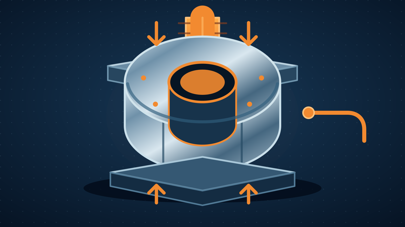
A donut load cell is an annular force sensor with a hole through its center, allowing a bolt, threaded rod, cable, shaft, or similar member to pass through the sensing body. Through-hole load cell, annular load cell, and sometimes load washer describe the same general form, although manufacturers may use those terms for different mechanical designs. The central opening is useful when force must be measured around an existing member, but reliable measurement depends on centered loading, flat interfaces, correct hardware, and qualified installation.
Key takeaways
- “Donut” describes the annular shape; through-hole is the common functional synonym.
- Models may be intended for compression, tension, or both, and those modes are not interchangeable.
- The sensor must be selected around the complete load path, not only the hole diameter and capacity.
- Flat, rigid, parallel interfaces and axial force introduction help prevent bending and edge loading.
- Preload, fasteners, adapters, cable routing, instrumentation, and environmental protection all affect the system.
- Installation and calibration should follow manufacturer instructions and be handled by qualified personnel.
Donut, through-hole, annular, and load-washer terminology
All four names point toward a ring-shaped sensor, but they are not universal product classes. A compact load washer may be intended to monitor bolt force in compression. A larger through-hole cell may sit around a tie rod in a test frame. Another annular design may use threaded adapters or retainers to measure tension. Two products that look similar can have different intended supports, force directions, overload behavior, sealing, outputs, and installation requirements.
Treat “donut load cell” as the starting description, then verify the manufacturer’s drawing and data sheet. The important questions are:
- What direction and type of force is rated?
- Which surfaces introduce and react the load?
- Does a member merely pass through the hole, or does it transfer force to the sensor?
- Is preload required or permitted?
- What hardware and mating surfaces are specified?
That distinction prevents the central hole from being mistaken for a universal mounting feature.
How an annular load cell measures force
Many donut load cells use strain gauges bonded to a machined elastic element. Axial force creates a small, repeatable deformation in the ring. The gauges change resistance, and a bridge circuit produces an electrical signal related to force. Instrumentation supplies excitation, conditions the signal, and converts the calibrated response into engineering units.
The basic sensing principle is shared with the broader strain-gauge family explained in our guide to how load cells work. What is distinctive here is the geometry: the opening permits a load-bearing or guiding member to occupy the centerline while the surrounding ring senses force.
Not every annular sensor uses the same internal structure or output. Some include integrated electronics; others provide a low-level analog bridge signal. Connection, excitation, amplification, sampling, and environmental requirements must therefore come from the model documentation rather than from a generic color code or assumed signal range.
Common applications
Through-hole designs are useful when conventional beam or column cells would obstruct the mechanism. Typical applications include:
- monitoring clamping or bolt force in qualified joint arrangements;
- measuring tie-rod or anchor forces;
- compression testing around a centered guide or specimen fixture;
- force monitoring in presses, actuators, and assembly tooling;
- cable, wire, or tendon test systems using engineered adapters;
- research fixtures where access through the sensor center is essential.
These examples do not make every donut cell suitable for every application. A safety-critical fastener, permanent structural anchor, dynamic machine, or lifting arrangement needs application-specific engineering. Confirm whether the sensor is intended for continuous monitoring, temporary testing, static force, cyclic duty, or another defined use.
Selection factors beyond capacity
Capacity is only one part of selection. First define maximum working force, preload, transient force, dynamic effects, and the minimum force change that must be detected. A high-capacity sensor may survive the load yet provide inadequate useful sensitivity for the measurement task. Conversely, choosing close to the routine force without accounting for assembly preload or credible transients can risk overload.
| Selection factor | What to confirm |
|---|---|
| Loading mode | Compression, tension, or bidirectional rating for the exact configuration |
| Central opening | Clearance, alignment, tolerances, and whether contact with the passing member is permitted |
| Interfaces | Required plates, washers, spherical seats, retainers, threads, or adapters |
| Force range | Working load, preload, transients, overload limits, and useful measurement span |
| Performance | Manufacturer-stated repeatability, nonlinearity, hysteresis, and temperature effects |
| Electrical system | Output, excitation, connector, cable, amplifier, indicator, and data acquisition compatibility |
| Environment | Temperature, moisture, dust, corrosion, chemicals, vibration, and cable exposure |
| Evidence | Calibration documentation, serviceability, and any required approvals |
Hole diameter must leave the clearance specified by the manufacturer. Unintended contact between the central member and sensor can create friction, side load, or a parallel force path. External diameter and height also matter because surrounding parts need clearance as the assembly loads and deflects.
Qualified installation: control the load path
A donut load cell should receive force through its intended loading faces and axis. Rough, tilted, flexible, or mismatched interfaces can concentrate stress at one edge and introduce bending. Unless the product documentation says otherwise, the basic objective is a clean, rigid, centered stack with mating surfaces that remain appropriately flat and parallel under load.
A qualified installation process should include:
- Review the complete assembly. Use the sensor drawing, equipment documentation, and an engineered load-path plan. Identify how force reaches the cell and where it reacts.
- Make the equipment safe. Isolate energy, remove or support loads by an approved method, and control stored mechanical energy before disturbing the assembly.
- Inspect mating parts. Check the specified surfaces, hardware, clearances, alignment, and condition. Do not install onto burrs, debris, distorted plates, or improvised spacers.
- Orient and assemble as documented. Follow the rated loading direction, fastener or retainer method, specified torque sequence, and any preload procedure. Do not use the cable to position the cell.
- Protect the signal path. Provide cable strain relief and route wiring away from pinch points, abrasion, heat, and electrical interference in accordance with system documentation.
- Load in a controlled manner. Observe for unexpected movement, contact, unstable zero, or nonrepeatable response before progressing through the intended range.
- Calibrate or verify the complete chain. Include the sensor, instrumentation, installed interfaces, and relevant software settings.
There is no universal torque, plate thickness, surface finish, or preload value. Those details depend on the sensor and joint design. Substituting generic values can overload the cell, alter the force distribution, or compromise the structure.
Common installation errors
Off-axis loading is a leading concern. A rod that enters at an angle, unequal plate support, or a cell trapped against nearby structure can add bending that the calibration did not represent. Force shunting occurs when another contact path carries part of the force around the sensor, causing under-reading or inconsistent results.
Other errors include using the wrong loading face, allowing the central member to rub the bore, applying unapproved fastener torque, welding near an installed cell without controls, twisting the cable, and assuming a display reset corrects mechanical problems. Changing zero or calibration to hide binding does not repair the load path.
If readings drift, jump, fail to return to zero, or change when the cable moves, remove the measurement from critical service and investigate systematically. The load cell troubleshooting guide outlines a mechanical-first sequence. Replacement or wiring work should be followed by appropriate calibration and verification.
Commissioning checklist
- Confirm sensor identity, loading mode, capacity, drawing, and calibration status.
- Verify central-hole clearance and absence of unintended contact.
- Inspect loading faces, adapters, supports, alignment, and structural condition.
- Apply approved isolation and stored-energy controls.
- Follow the documented orientation, hardware, torque, and preload procedure.
- Protect the connector and cable with suitable routing and strain relief.
- Confirm compatible excitation, conditioning, display, and data settings.
- Check zero, repeatability, return to zero, and response under controlled force.
- Verify the installed system against application requirements and retain records.
This is general guidance, not a structural or installation specification. Donut load cell selection and installation should be reviewed by qualified mechanical and instrumentation personnel, with manufacturer instructions and applicable site, legal, and safety requirements controlling the work.
Frequently asked questions
Is a donut load cell the same as a through-hole load cell?
The terms are commonly used for the same broad annular form: a sensor with a central opening through which a bolt, rod, cable, or other member can pass. Product terminology varies, so confirm loading mode, geometry, and specifications rather than relying on the name alone.
Can a donut load cell measure both compression and tension?
Some designs measure compression only, while others are configured for tension or bidirectional force. The load path, retainers, adapters, and calibration must match the rated mode. Never assume a compression washer can safely measure tension.
Can I use a donut load cell as a structural washer?
Only if the manufacturer explicitly designs and documents it for that installation. A sensor is not automatically a substitute for an ordinary washer or structural component. The joint and load path require qualified engineering review.
Does a donut load cell need calibration after installation?
The sensor requires a valid calibration, and the assembled measurement chain should be verified in its installed configuration. Interfaces, preload, alignment, cabling, instrumentation, and structure can influence the practical result.
Related guides

Wireless Load Cells: Selection, Radio, Power, and Security
Understand wireless load cell architecture, radio reliability, battery planning, cybersecurity, calibration, and selection without relying on range claims.
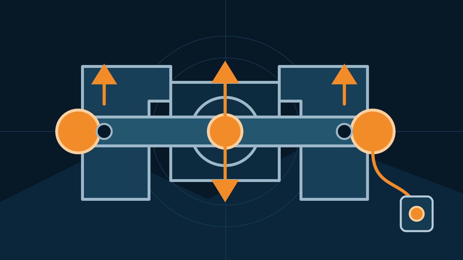
Load Pin: Operation, Selection, Installation, and Safety
Learn how a load pin measures force in clevis and pinned joints, what affects accuracy, and how to specify, install, calibrate, and inspect one safely.
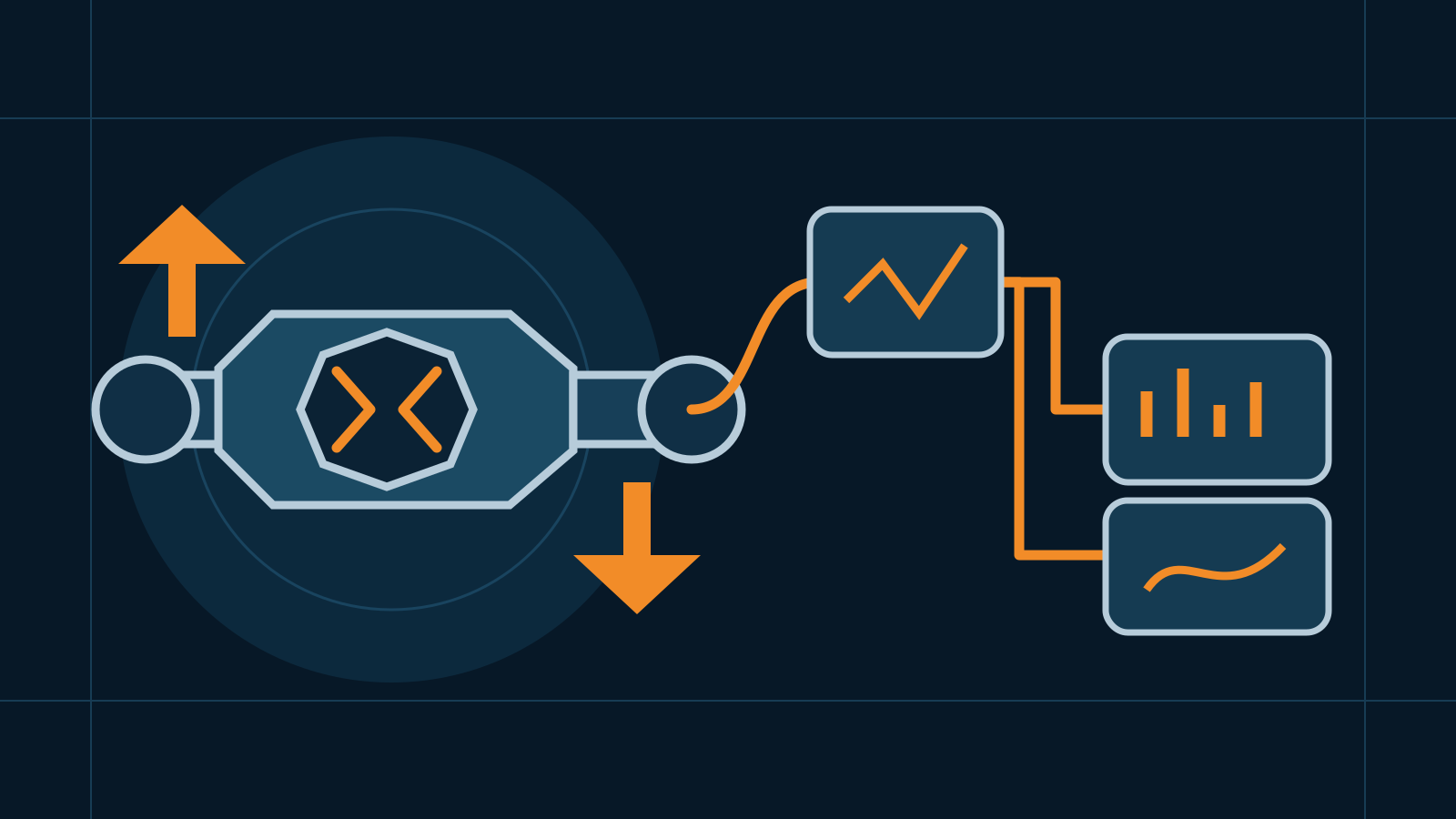
Force Transducer: How It Works and How to Select One
Understand what a force transducer does, how it differs from a load cell and dynamometer, and how to specify the sensor, electronics, mounting, and calibration.