Load Pin: Operation, Selection, Installation, and Safety
Learn how a load pin measures force in clevis and pinned joints, what affects accuracy, and how to specify, install, calibrate, and inspect one safely.
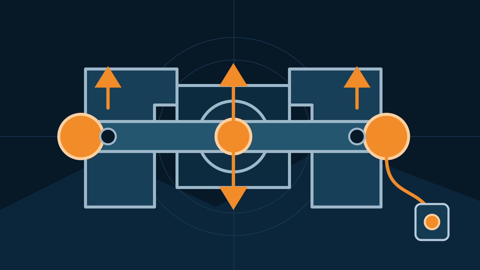
A load pin is a purpose-designed, instrumented pin that both carries force in a pinned joint and produces a measurement signal. It can monitor a clevis, sheave, shackle, pivot, hoist, winch, hydraulic cylinder connection, or other engineered assembly. It is not a standard pin with a sensor added casually, and a structural pin must never be replaced by an improvised load pin based on diameter alone.
Key takeaways
- A load pin combines a load-bearing mechanical function with force measurement.
- Joint geometry, bearing locations, retention, orientation, and anti-rotation details influence both strength and measurement.
- A same-diameter replacement is not automatically mechanically or metrologically compatible.
- Selection should address load cases, fatigue, environment, signal, cable routing, calibration, inspection, and safe failure consequences.
- Final-assembly calibration or verification may be necessary because the surrounding joint affects response.
How a load pin measures force
A typical instrumented load pin contains strain gauges positioned in machined sensing zones inside the pin. When the joint applies force through its bearings, the pin bends or shears by a small elastic amount. The gauges change resistance, and a bridge circuit generates an output related to the applied force. Internal cavities are sealed, and the signal exits through an integral cable, connector, or protected electronics housing.
This arrangement puts the sensor directly into an existing-style load path and can save space compared with adding an external inline transducer. The tradeoff is that the pin’s behavior depends strongly on the joint around it. Bearing width and spacing, clearances, support symmetry, lubrication, restraint, load direction, and pin rotation can change the strain distribution. A calibration from a different fixture may not represent the final installation.
Where load pins are used
Load pins can be considered where force already passes through a pin and where the joint can be engineered around an instrumented component. Examples include:
- sheave and pulley shafts used to infer line tension;
- clevis joints on cylinders, actuators, and test equipment;
- cranes, hoists, winches, and lifting attachments;
- anchor points and mooring or towing equipment;
- cable handling and tension-monitoring machinery;
- industrial pivots where force feedback supports process monitoring.
The measured quantity is not always identical to the desired process quantity. A sheave pin may sense the resultant force at the pin, while the required line tension depends on rope direction and geometry. Friction and changing wrap angle can also matter. The system designer should establish the force relationship rather than applying a convenient conversion universally.
Load pin vs load cell
A load pin is a type of force transducer and may be described as a load cell, but its mechanical role is distinctive. Conventional load cells are often installed beneath a platform, in tension between adapters, or against a reaction surface. A load pin replaces a specifically engineered pin within a bearing joint and must satisfy both sensing and structural requirements.
| Aspect | Load pin | Conventional inline or reaction load cell |
|---|---|---|
| Load path | Through a pinned joint and bearing zones | Through designed loading faces, threads, rods, or mounts |
| Mechanical role | Often functions as a structural pin | Usually functions as a dedicated sensing element within separate hardware |
| Installation influences | Bearing spacing, fit, rotation, retention, support symmetry | Alignment, contact, base stiffness, adapters, side load |
| Integration benefit | Compact measurement at an existing joint location | Broad choice of standard packages and accessories |
| Key caution | Structural substitution requires engineering approval | Mounting must follow the specific sensor design |
For the wider measurement-chain context, see the guide to selecting a force transducer.
Information needed to specify a load pin
A supplier or engineer needs more than nominal diameter and working load. Gather the following before requesting a design:
Mechanical arrangement
Provide drawings of the joint, lug and clevis dimensions, bearing widths and spacing, pin length, fits, retention method, available anti-rotation features, and surrounding clearance. Identify whether the pin rotates in service and whether bushings, bearings, lubrication passages, or keeper plates are present.
Complete load cases
Define normal force, direction, reversals, preload, shock, vibration, side load, bending, expected cycles, and credible abnormal conditions. Include forces associated with installation, transport, snagging, misalignment, and machine operation where relevant. The responsible engineer should evaluate static strength, fatigue, bearing stress, deflection, and the consequences of failure.
Measurement objective
State whether the output supports trending, overload indication, closed-loop control, load distribution, testing, or a reported calibrated value. Define the useful range, required repeatability and uncertainty, response needs, units, and how alarms or decisions will be made. A safety-related function may require architecture beyond one measurement channel.
Environment and interface
Document temperature, moisture, immersion, washdown, corrosion, chemicals, dust, hazardous-area constraints, electromagnetic interference, and mechanical damage risks. Specify cable exit direction, connector access, protective routing, service loops, amplifier or indicator compatibility, and whether integrated or remote electronics are preferred.
Selection and design checklist
- Confirm the pin is engineered for the actual joint, not merely the same nominal diameter.
- Review material, heat treatment, geometry, surface finish, fits, and bearing interfaces as a complete design.
- Define retention and anti-rotation without drilling or modifying the sensor in the field.
- Check that cable or connector placement cannot foul moving parts or become a handhold.
- Evaluate every relevant direction and operating state, including reversed or off-axis forces.
- Agree on the calibration fixture and whether installed calibration is required.
- Plan inspection access and criteria before the pin enters service.
- Determine what the machine should do if the signal is lost, implausible, or out of range.
Measurement capacity and structural capacity are related but not interchangeable labels. Likewise, an overload rating on a data sheet is not a substitute for analysis of fatigue, impact, or the complete assembly. Obtain written drawings and specifications for the exact manufactured configuration.
Installation: preserve the engineered load path
Installation should follow an approved procedure from the equipment and load-pin manufacturers. Before work begins, isolate all relevant energy, remove or securely support the load, establish an exclusion zone, and verify that the structure cannot move unexpectedly. Lifting or blocking arrangements should be designed for the actual equipment; do not rely on hydraulic pressure or the component being removed as sole personnel protection.
Inspect the lugs, bores, bushings, retainers, and adjacent structure for wear, distortion, cracks, corrosion, or misalignment. Forcing a new pin through damaged or misaligned bores can harm the sensor and conceal a structural defect. Do not hammer the connector, pull on the cable, grind the body, weld nearby without approved controls, or add unapproved grooves and holes.
Install the specified orientation and retention components. If the pin has marked sensing axes or an anti-rotation feature, their relationship to the force direction matters. Route the cable away from pinch points, abrasion, hot surfaces, sharp bends, and moving members while allowing the required joint movement. Seal connectors using the prescribed components, not improvised compounds that can trap moisture or hinder inspection.
A load cell replacement involves similar energy-control and commissioning principles, but it does not replace the joint-specific engineering needed for a pin.
Calibration and commissioning
A useful calibration reproduces the installed support and loading conditions as closely as practical. A generic fixture may be adequate for some applications; others need calibration in a representative clevis or verification after assembly. Apply force through the intended path and record pin orientation, fixture dimensions, electronics, settings, temperature, reference equipment, load sequence, and results.
Commissioning may include zero stability, multiple applied-force points, increasing and decreasing loads, repeatability, rotation or position checks, alarm tests, and comparison with process behavior. The appropriate sequence and acceptance limits depend on the measurement purpose. If a result differs from the calibration fixture, investigate joint geometry, binding, cable force, restraint, alignment, and signal configuration rather than correcting every difference with an undocumented scaling change.
Inspection and safe operation
Treat the load pin as both an instrument and a load-bearing component. Establish inspections based on the equipment maker’s instructions, duty, environment, history, and applicable requirements. Look for physical damage, corrosion, wear at bearing zones, retainer problems, unexpected rotation, cable abrasion, connector damage, moisture entry, zero shifts, unstable output, and unexplained differences from other process information.
Remove the equipment from service when damage, overload, structural change, or questionable readings could affect safety. Do not straighten, weld, plate, machine, or reseal the pin as a field repair unless an approved manufacturer procedure specifically permits it. Signal plausibility checks can help identify faults, but an indicated value does not by itself prove structural integrity.
This is general guidance, not authorization to modify lifting or load-bearing equipment. A competent engineer should approve the load pin and surrounding joint, and qualified personnel should install, calibrate, inspect, and return the assembly to service under manufacturer instructions and applicable site or jurisdictional requirements.
Frequently asked questions
What is a load pin?
A load pin is an instrumented pin designed to carry load in a pinned joint while producing a signal related to the applied force. It is commonly integrated into clevises, sheaves, shackles, pivots, and other engineered assemblies.
Can a standard structural pin be replaced with a load pin of the same diameter?
Not without an engineering assessment and an approved design. Diameter alone does not establish strength, fatigue performance, fit, retention, bearing behavior, environmental suitability, or measurement performance. An improvised substitution can make the joint unsafe.
Why can a load pin reading change after installation?
Joint geometry, bearing distribution, pin rotation, restraint, side load, friction, alignment, cable forces, temperature, and the calibration setup can affect response. Calibration or verification in the final assembly may be needed.
How should a load pin be calibrated?
The method should reproduce the installed loading and support conditions as closely as practical, using suitable reference equipment and a documented procedure. Requirements depend on the application, risk, manufacturer guidance, and any applicable jurisdiction or quality system.
Related guides

Wireless Load Cells: Selection, Radio, Power, and Security
Understand wireless load cell architecture, radio reliability, battery planning, cybersecurity, calibration, and selection without relying on range claims.
Donut Load Cells: Through-Hole Design and Installation
Learn how a donut load cell, also called a through-hole load cell, measures compression or tension and what reliable, qualified installation requires.
Force Transducer: How It Works and How to Select One
Understand what a force transducer does, how it differs from a load cell and dynamometer, and how to specify the sensor, electronics, mounting, and calibration.