Load Cell Replacement: Selection, Installation and Calibration
Plan a safe load cell replacement: confirm the fault, match mechanical and electrical requirements, install correctly, then calibrate and verify the scale.
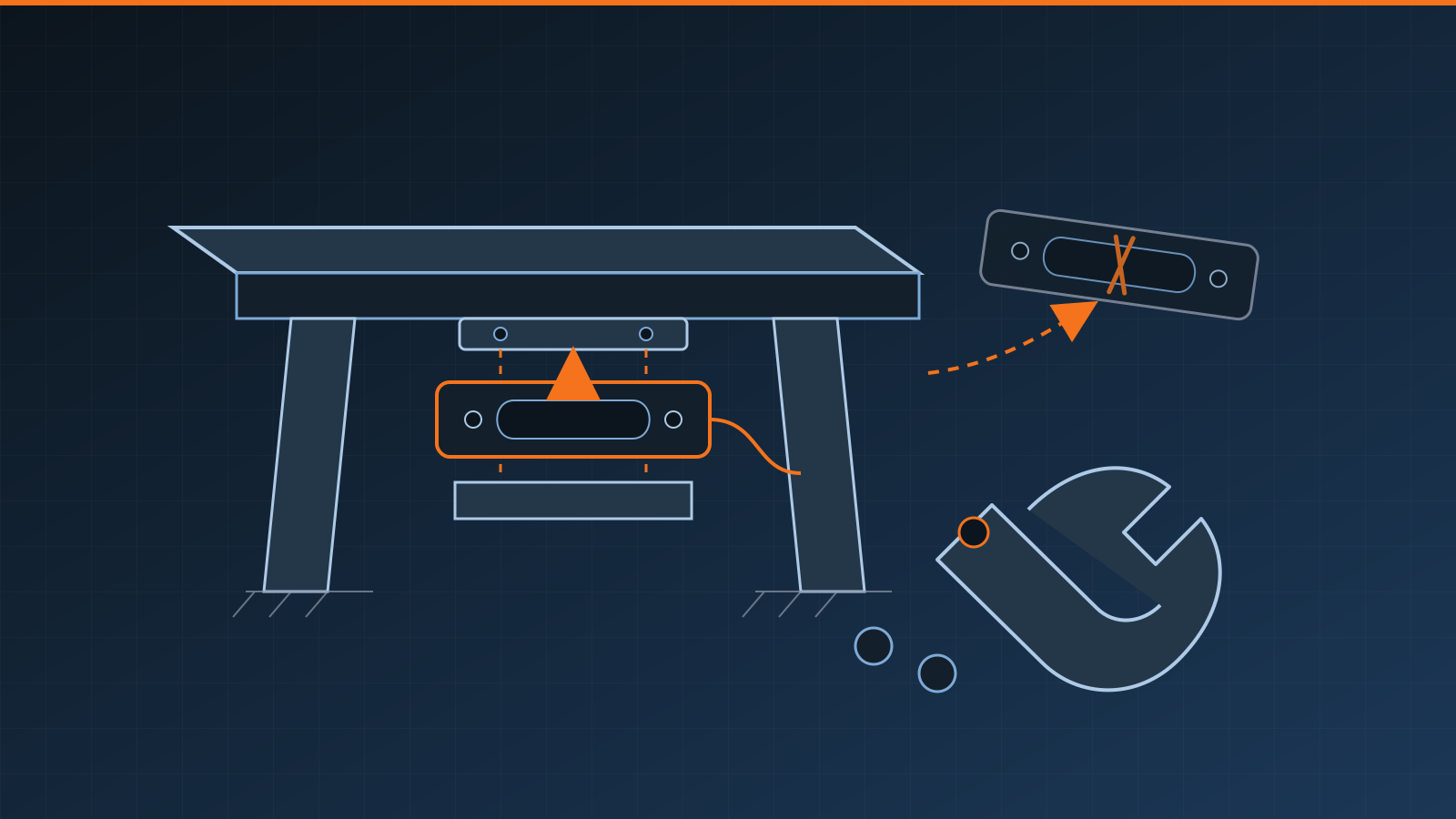
A load cell replacement should begin only after the fault is confirmed and a compatible replacement is specified. The safe process is to remove the scale from service, control electrical and mechanical energy, support the structure by an approved method, have a qualified technician install the cell without changing the intended load path, then corner-balance, calibrate and verify the complete instrument. Replacing a sensor by appearance or bolt pattern alone can create inaccurate readings, mechanical damage or an invalid approved configuration.
Key takeaways
- Diagnose the system before ordering a cell; binding, cable damage, moisture or an indicator fault can imitate sensor failure.
- Match capacity, loading mode, rated output, bridge characteristics, mounting geometry, environment and approvals.
- Apply site lockout/tagout and engineered support controls before disturbing a load-bearing component.
- Protect the new sensor from impact, twisting, welding current, contamination and cable strain.
- In a multi-cell system, check corner response before final calibration.
- Record the as-found fault, part identity, work performed, calibration results and return-to-service authorization.
Confirm replacement is the right repair
A bad reading does not prove that the sensing element has failed. Debris can bridge a platform, a restraint can bind, a mount can shift, a cable can be crushed, moisture can enter a junction box, or an indicator input can become unstable. Replacing the cell without isolating the cause may leave the same symptom in place and destroy useful diagnostic evidence.
Start with the symptom, recent events and service history. Record whether the problem affects zero, span, repeatability, one corner or every reading. Note impacts, overloads, flooding, washdown, temperature changes, maintenance and electrical work. Inspect the load path, mounting hardware, cable route, connectors and enclosures under safe site procedures. Our load cell troubleshooting guide provides a mechanical-first diagnostic sequence without treating live electrical work as a do-it-yourself test.
A qualified technician can then compare the suspected channel with system documentation and suitable test equipment. Permanent deformation, a nonresponsive bridge, unstable behavior isolated to one cell, damaged sealing, or an irreparable integral cable may support replacement. A loose terminal, damaged removable cable or defective mount may instead have an approved repair. Do not drill, grind, weld, bend or reseal a sensor body as an improvised fix.
Replacement load cell compatibility checklist
“Same capacity” does not mean “interchangeable.” Review the complete data sheets, drawings, approvals and indicator requirements.
| Compatibility factor | What to confirm | Why it matters |
|---|---|---|
| Capacity and overload ratings | Required working range, preload and anticipated dynamic or accidental loads | Undersizing risks damage; casual oversizing can reduce usable system sensitivity |
| Loading mode | Compression, tension, shear, bending or other intended force direction | A different sensing geometry may not carry or measure the load correctly |
| Rated output and tolerance | Signal sensitivity and matching requirements for the system | Mismatch can limit calibration or corner-balancing capability |
| Bridge characteristics | Input/output resistance, excitation limits, sense arrangement and cell technology | The indicator, junction equipment and other cells must support the electrical load and signal |
| Mounting geometry | Dimensions, threads, hole pattern, load introduction points and required hardware | Poor fit can add side load, bind the structure or alter alignment |
| Environment | Temperature range, sealing, washdown, corrosion, chemicals, vibration and cable exposure | The enclosure claim alone does not address every operating hazard |
| Approvals | Legal-for-trade, hazardous-location, hygienic or other required system status | Substitution can invalidate an approved configuration or protection concept |
| Cable and termination | Length, conductor arrangement, gland, connector and routing | Cable changes can affect performance, sealing and serviceability |
Also check whether the system requires a matched set or manufacturer-authorized replacement. In multi-cell analog scales, differences that appear small on individual data sheets can consume junction-box trim range. In digital systems, addressing, firmware, communication and configuration may also control compatibility.
For regulated, hazardous or safety-related applications, use the approved documentation and consult the manufacturer, authority having jurisdiction or qualified provider. Written confirmation is more defensible than assuming a “universal” cell will preserve the installation’s status.
Safety and lockout before removal
A load cell is often part of a load-bearing assembly. Electrical isolation alone does not make the work safe. Platforms, hoppers, tanks and suspended assemblies can move, settle or release stored energy when hardware is loosened.
The site-specific plan should address:
- removing the instrument and connected process from service;
- lockout/tagout of electrical, pneumatic, hydraulic and process energy as applicable;
- emptying or stabilizing the weighed structure;
- engineered blocking, lifting or support at approved points;
- controls for pits, confined spaces, elevated work and mobile equipment;
- exclusion zones and communication with operations;
- protection of legal seals, settings and records.
Never rely on a jack, hoist or hydraulic pressure alone as permanent personnel protection. Do not work beneath an inadequately supported structure. A competent person should approve the support and lifting method for the actual equipment and site.
Qualified installation procedure
The exact load cell replacement procedure comes from the scale, mount and sensor manufacturers. At a high level, qualified personnel should:
- Preserve evidence. Record the as-found reading, cell identification, cable routing, terminal identification, orientation, mount condition and authorized configuration before disassembly.
- Make the assembly safe. Apply the approved energy-control and structural-support plan, then confirm the load is removed from the cell.
- Inspect the surrounding system. Correct corrosion, distorted plates, damaged restraints, poor drainage, cable abrasion or the overload source. A new cell should not be installed into a condition that caused the old one to fail.
- Remove without collateral damage. Avoid forcing seized parts in ways that distort the structure. Protect junction equipment and nearby electronics from conductive debris, impact and unauthorized current paths.
- Install the specified components. Follow the documented orientation, torque, alignment, clearances and hardware requirements. Do not substitute ordinary fasteners, spacers or mounting parts where engineered components are required.
- Route and terminate the cable correctly. Maintain bend radius, strain relief, sealing, physical protection and separation from interference sources. Never infer conductor function from color alone.
- Perform a controlled mechanical review. Confirm that load introduction, restraints, stops and surrounding structures allow intended movement without side loading or binding.
This is deliberately not a live-wiring guide. Wiring arrangements, excitation, intrinsic-safety barriers, grounding and test methods vary. Circuits should be isolated as required, identified from current documentation and handled with suitable equipment by qualified personnel.
Cornering, calibration and verification
After installation, zeroing the display is not enough. In a multi-cell platform, place suitable known loads at the required positions and evaluate corner response. Correct mechanical errors first. Only then should a technician use the documented trim method in the load cell junction box or approved digital configuration. Trimming must not hide binding, a poor mount or an incompatible cell.
Calibrate the assembled instrument over the required working range with appropriate traceable references. The procedure may include increasing and decreasing loads, repeatability, eccentric loading and other tests based on the scale type and intended use. Preserve as-found results before adjustment whenever possible, and record as-left results, uncertainty and applied tolerances.
Verification is the decision that the scale meets specified requirements after calibration or adjustment. Commercial, safety-related and quality-controlled applications may also require inspection, sealing or authorization by a relevant authority. Do not return the scale to service until the required acceptance criteria and operational checks are complete.
Replacement records and service planning
Close the work order with the asset and location, symptom, diagnosis, removed and installed cell identifiers, specifications reviewed, mount or cable repairs, authorized configuration changes, technician, date, test equipment, corner results, calibration results and return-to-service approval. Attach photographs or drawings when they improve future identification.
Update the spare-parts list and failure history. Repeated failures at one position may indicate impact, water entry, structural misalignment, lightning exposure, cable damage or an unsuitable environmental specification rather than random sensor defects. A qualified scale service and calibration provider can diagnose the root cause, source a compatible replacement, complete controlled installation and produce one defensible record for the entire job.
Frequently asked questions
Can I replace a load cell with a different model?
Only when the replacement is demonstrably compatible with the complete weighing system. Capacity, rated output, bridge characteristics, loading mode, mounting geometry, environmental protection, approvals and indicator compatibility all matter. A qualified scale provider should review the specifications and system documentation.
Does replacing a load cell require recalibration?
Yes. Replacing a load cell changes a critical measurement component, so the assembled scale should be corner-balanced where applicable, calibrated with suitable traceable references, and verified against the requirements for its application before return to service.
Should every load cell in a multi-cell scale be replaced together?
Not automatically. One confirmed failed cell may be replaceable on its own when a compatible part is available and the other cells remain sound. Replace multiple cells when condition, compatibility, history or manufacturer guidance supports it, then balance and calibrate the complete system.
Who should replace a load cell?
A qualified scale technician should perform or supervise the work. The task can involve stored mechanical energy, heavy structures, restricted access, sensitive measurement wiring and regulated configurations, as well as calibration and return-to-service decisions.
Related guides
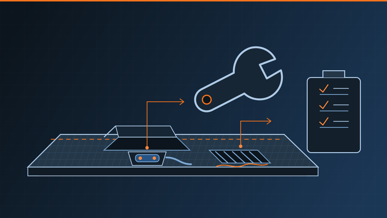
Truck Scale Maintenance: Inspection and Service Checklist
Use this truck scale maintenance checklist to inspect drainage, deck gaps, load cells, cables, grounding, approaches, and software while planning service.
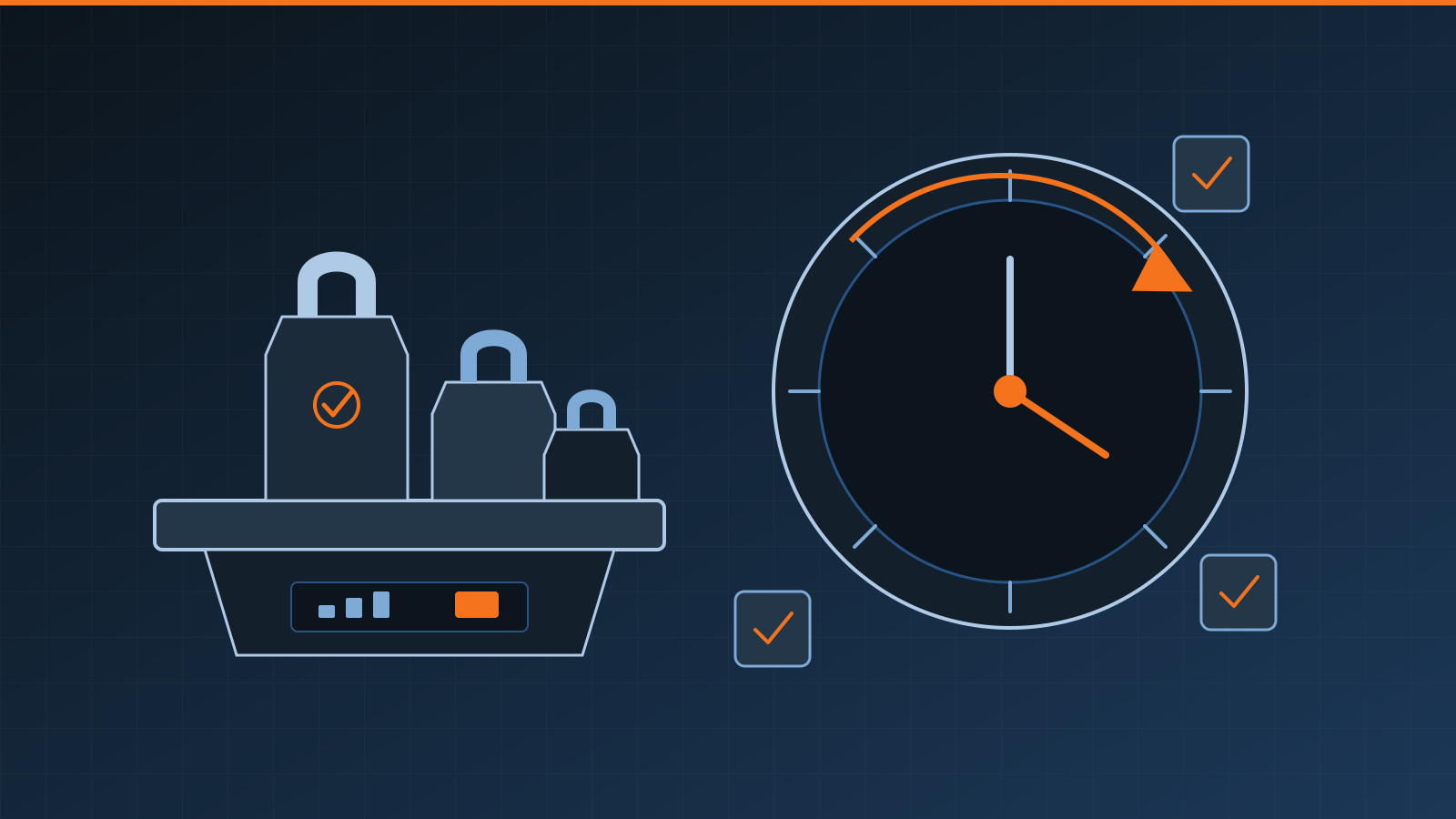
Scale Calibration Frequency: How to Set the Right Interval
Learn how often to calibrate a scale using a risk-based interval based on use, impact, drift, environment, regulations and documented performance history.
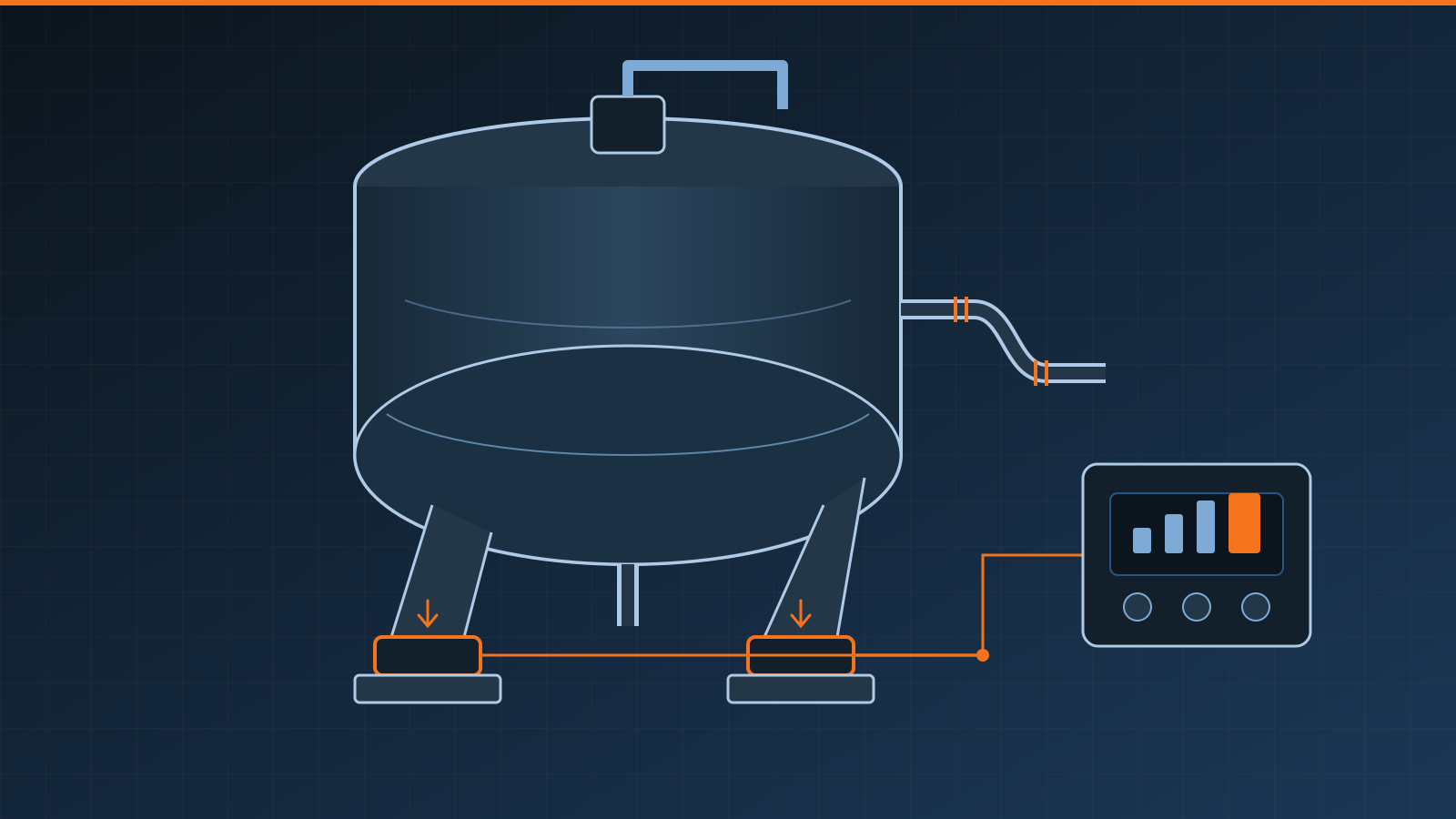
Tank Weighing System: Components, Installation, and Selection
Learn how a tank weighing system works, which components it needs, how piping and agitation affect readings, and how to plan installation and calibration.