Load Cell Troubleshooting: A Structured Diagnostic Guide
Troubleshoot load cell faults in a safe sequence: document symptoms, inspect mechanics and wiring, then have a qualified technician test excitation and signal.
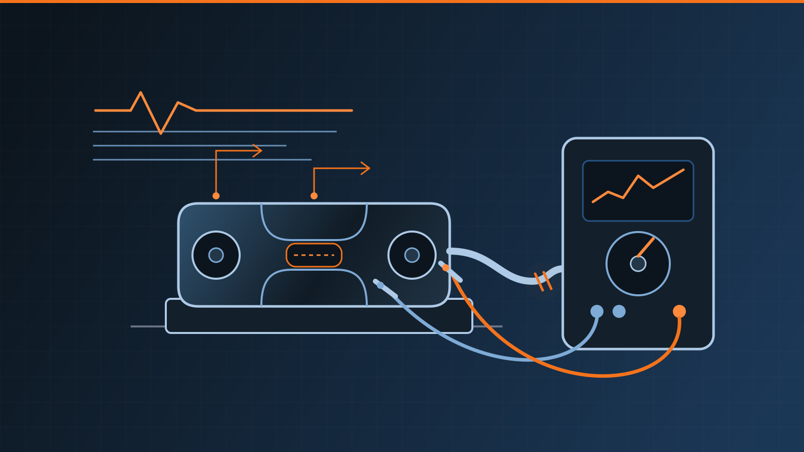
Load cell troubleshooting should follow a controlled sequence: record the symptom and operating conditions, make the equipment safe, inspect the mechanical load path, inspect cables and connections, and only then have a qualified technician evaluate excitation and signal behavior. This order prevents electrical adjustments from masking binding, overload damage or other physical faults. There is no universal acceptable resistance, voltage or signal range; use the documentation and criteria for the specific load cell and instrument.
This is general diagnostic guidance, not a live-wiring procedure. Follow site energy-control rules, manufacturer instructions and applicable electrical and machine-safety requirements. Remove a weighing or force-measuring system from service when a fault could affect a safety decision, process control, billing or compliance.
Key takeaways
- Start with the exact symptom, history and conditions, not a guessed failed component.
- Rule out mechanical interference and loading problems before changing calibration or trim.
- Inspect the full cable route, connectors and enclosures for damage, moisture and loose terminations.
- Excitation and signal tests require compatible documentation, suitable instruments and a qualified technician.
- Do not apply unverified test voltages, bypass protective circuits or improvise sensor repairs.
- Any repair, cell replacement or adjustment should be followed by appropriate calibration and verification.
Symptom-to-cause quick reference
Use symptoms to prioritize checks, not to declare a diagnosis.
| Symptom | Possible mechanical causes | Possible electrical or measurement causes |
|---|---|---|
| Unstable or jumping reading | Vibration, contact with surrounding structure, loose mount, moving product | Loose connection, cable damage, moisture, interference, unstable excitation |
| Zero drift | Thermal movement, debris buildup, changing pipe or restraint forces, load left on system | Moisture, insulation breakdown, connection fault, sensor or indicator instability |
| Does not return to zero | Binding, trapped material, impact or overload deformation | Damaged cell, cable fault, changed configuration or inappropriate adjustment |
| Incorrect span or sensitivity | Changed load path, friction, support problem, mechanical modification | Wrong configuration, cell mismatch, partial circuit fault or calibration issue |
| Non-repeatable result | Load applied differently, rocking structure, unstable foundation, friction | Intermittent conductor, connector fault, electrical noise or failing component |
| One corner differs | Debris, damaged mount, uneven support, structural contact | One cell/channel fault, summing connection or trim issue |
| No response or fixed extreme reading | Load not reaching the cell, hard mechanical stop | Missing excitation, open/short circuit, incorrect wiring, indicator input fault |
Several causes can exist at once. For example, water can corrode a terminal while debris under the deck changes the load path. Correcting only one may improve the symptom without restoring dependable measurement.
Step 1: Define and document the symptom
Before disturbing the system, record what the operator sees:
- Does the fault affect zero, span, repeatability, one corner or the entire reading?
- Is it constant or intermittent?
- Does it follow rain, washdown, temperature change, startup, nearby machinery or cable movement?
- Did it begin after an overload, impact, relocation, maintenance, electrical work or component replacement?
- Does the displayed value correspond to a real process change, vibration or material accumulation?
- Are there alarms, error messages or recent calibration records?
Capture the equipment identity, indicator configuration if authorized, operating state and as-found reading without making speculative adjustments. Historical calibration results can show whether the fault developed gradually or appeared suddenly. A useful certificate records the distinction between as-found and as-left performance.
If the system controls lifting, batching, overload protection or commercial transactions, establish an approved alternative before taking it out of service. Do not keep operating merely to collect more evidence when the reading may be unsafe or materially wrong.
Step 2: Inspect the mechanical installation
A load cell measures the force that actually passes through its designed axis. It cannot distinguish intended load from side force, binding, pipe restraint or a structure touching a fixed object.
With the equipment safely isolated and inspected under the relevant site procedure, look for:
- debris, ice or hardened product bridging a platform or vessel;
- a bent, shifted, loose or corroded mount;
- contact at check rods, bump stops, restraints, guards or surrounding structure;
- piping, conduit or flexible connections transmitting unintended force;
- a rocking base, damaged foundation or uneven support;
- impact, overload, heat or visible structural distortion;
- a cable pulled tight enough to influence or damage the cell connection.
Do not loosen load-bearing hardware, enter a pit, work beneath a raised structure or alter restraints without the required engineered controls and authorization. Do not force the system through its range to “free it up.” A qualified mechanical or scale technician should assess suspect mounts and structures.
If a known load gives different results depending on position, correct mechanical causes before corner adjustment. Trim is for balancing small channel differences in a sound system, not for hiding binding or a damaged support.
Step 3: Inspect wiring and environmental protection
Trace the accessible cable route from each load cell to its connector, junction equipment and indicator. Look for crushed, cut, abraded, stretched or heat-damaged cable; unsupported entries; loose glands; damaged connectors; unauthorized splices; corrosion; condensation; and evidence of flooding or washdown ingress.
Do not assume conductor function from color. Load cell wiring, sense conductors, shield treatment and grounding arrangements differ. Use current manufacturer drawings and verified cable identification. De-energize and isolate circuits as required before opening enclosures or touching terminations.
In a multi-cell analog scale, the load cell junction box is a common point for moisture, loose terminals and corner-related faults. Record trim positions or other settings before any authorized change. Cleaning corrosion, drying a board or tightening a terminal without finding the ingress or strain cause may produce only a temporary recovery.
Cable routing also matters. Measurement wiring installed near switching devices, motors or power conductors may pick up interference, especially when shielding or grounding is damaged. The remedy must follow the approved system design; adding an improvised ground can create another noise path or compromise electrical protection.
Step 4: Evaluate excitation and signal
Once mechanical and visible wiring issues have been addressed, a qualified technician can determine whether the indicator supplies the expected excitation and whether the sensor signal responds coherently to controlled loading. The correct test points, loading method, meter, isolation state and expected values come from the load cell and indicator documentation.
A useful diagnostic comparison asks:
- Is the excitation stable at the intended points and under the connected load?
- Does the no-load signal remain stable after the system settles?
- Does the signal change smoothly and in the expected direction when a safely controlled load is applied?
- In a multi-cell system, does one channel behave differently from comparable channels?
- Does the behavior change across a connector, junction box or cable section?
These questions localize the fault without publishing a supposed universal voltage, resistance or millivolt range. Electrical characteristics differ by sensor and system. Applying external excitation, testing insulation with an unsuitable instrument, shorting conductors or probing energized terminals can damage electronics, defeat protective barriers or create a shock and ignition hazard.
Swapping components may be appropriate only when a technician has confirmed compatibility and can preserve wiring, configuration and protection requirements. A successful substitution is diagnostic evidence, not permission to leave the system uncalibrated.
Diagnostic checklist for the service call
- Identify the asset, application, consequence of error and required service status.
- Record the exact symptom, timing, environmental conditions and recent events.
- Review manuals, wiring information, service history and calibration records.
- Apply site isolation, access and mechanical safety controls.
- Inspect the load path, mounts, restraints, foundation and surrounding structure.
- Inspect cables, connectors, glands, junction enclosures and indicator connections.
- Have a qualified technician perform documented excitation and signal checks.
- Correct the verified root cause using approved parts and procedures.
- Perform corner balancing where applicable, then calibrate the complete system.
- Record as-found findings, corrective work, as-left results and return-to-service approval.
Repair, replacement and calibration
Field-repairable faults may include an approved cable, connector, gland, junction board or indicator component, depending on manufacturer policy and the installation. Damage to a sealed load cell or deformed spring element is different. Do not drill, weld, grind, bend, reseal or splice the sensor body as an improvised repair. Obtain an assessment from the manufacturer or a qualified scale repair provider.
Replacement must match the mechanical fit, capacity and loading mode as well as electrical output, bridge characteristics, environmental protection, approvals and system architecture. “Fits the bolt pattern” is not enough. In multi-cell systems, channel matching and corner balance also matter.
After corrective work, calibrate the assembled instrument with suitable traceable references and document the results. Legal-for-trade, safety-related or quality-controlled applications may require additional verification or authorization based on jurisdiction and use. A qualified provider can combine root-cause diagnosis, approved repair, calibration and defensible return-to-service records.
The most efficient troubleshooting is rarely the fastest component swap. A symptom-first, mechanical-first and documented electrical approach finds the actual fault, avoids unsafe experimentation and gives the business evidence that the measurement system is reliable again.
Frequently asked questions
Why is my load cell reading unstable?
Possible causes include vibration, binding, changing loads, moisture, a loose or damaged cable, poor shielding or grounding, electrical interference, unstable excitation, or a failing sensor or instrument input. A structured mechanical and electrical assessment is needed to isolate the cause.
How do I know whether the load cell or indicator is faulty?
The symptom alone is not enough. A qualified technician can inspect the mechanical installation and wiring, then compare excitation and signal behavior at defined points using the manufacturer’s documentation and suitable test equipment. Substitution should use known-compatible equipment and be followed by calibration.
Can an overloaded load cell be repaired?
Overload can permanently deform the sensing element or damage internal strain-gauge circuits. Do not bend, grind or otherwise improvise a repair. The manufacturer or qualified scale provider should assess whether approved repair is possible or replacement is required, followed by calibration and verification.
Does replacing a load cell require recalibration?
Yes, the complete weighing system generally needs calibration after a load cell is replaced. Multi-cell systems may also need corner balancing before final calibration and any verification required for the application.
Related guides
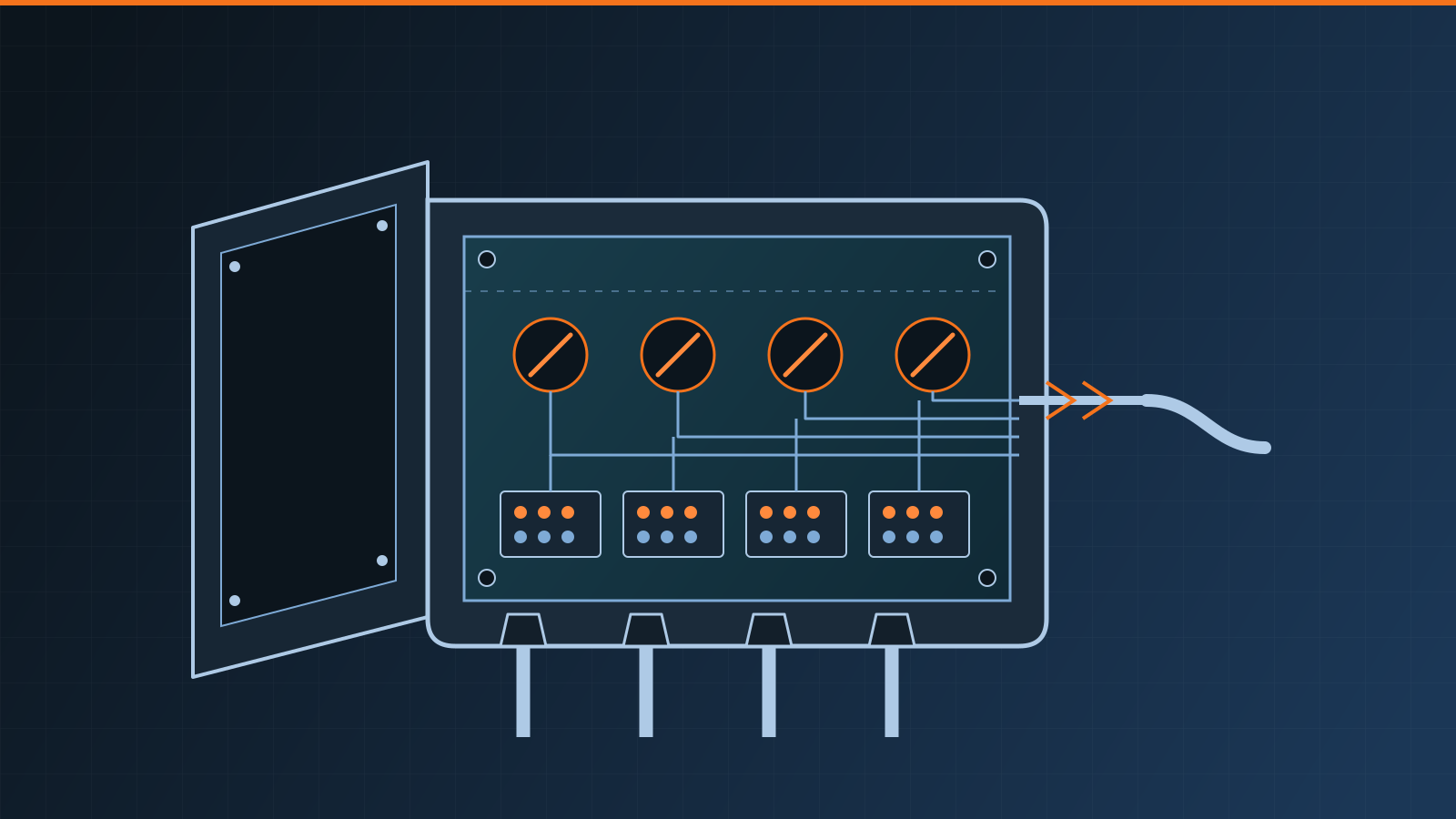
Load Cell Junction Boxes: Summing, Wiring and Corner Adjustment
Learn how a load cell junction box sums signals, supports corner adjustment, protects wiring, and what to check when selecting or troubleshooting one.
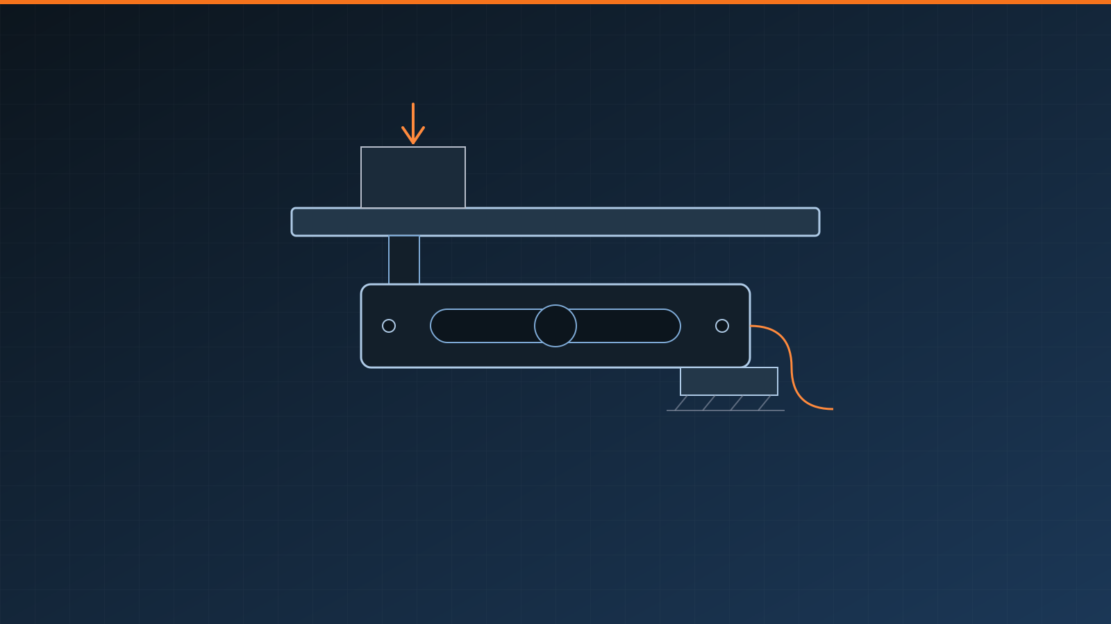
Single Point Load Cells Explained: How They Work and Where They're Used
What a single point load cell is, how it handles off-centre loading, where it is used, and how to select and mount one in small platform and bench scales.
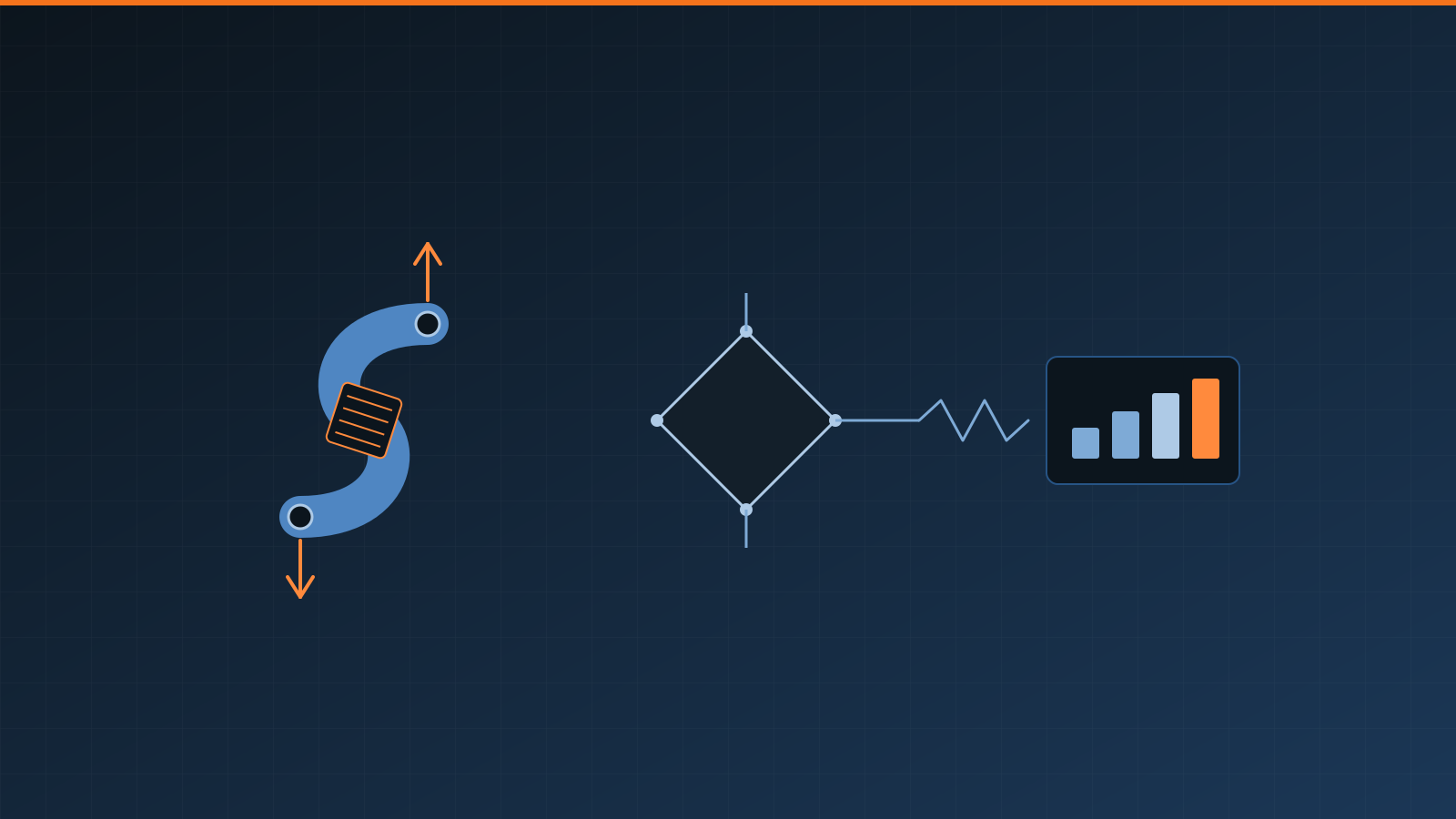
How Load Cells Work in Crane Scales and Dynamometers
A clear guide to the load cell at the heart of crane scales and dynamometers: how strain-gauge sensing works, what affects accuracy, and common signal issues.