Force Transducer: How It Works and How to Select One
Understand what a force transducer does, how it differs from a load cell and dynamometer, and how to specify the sensor, electronics, mounting, and calibration.
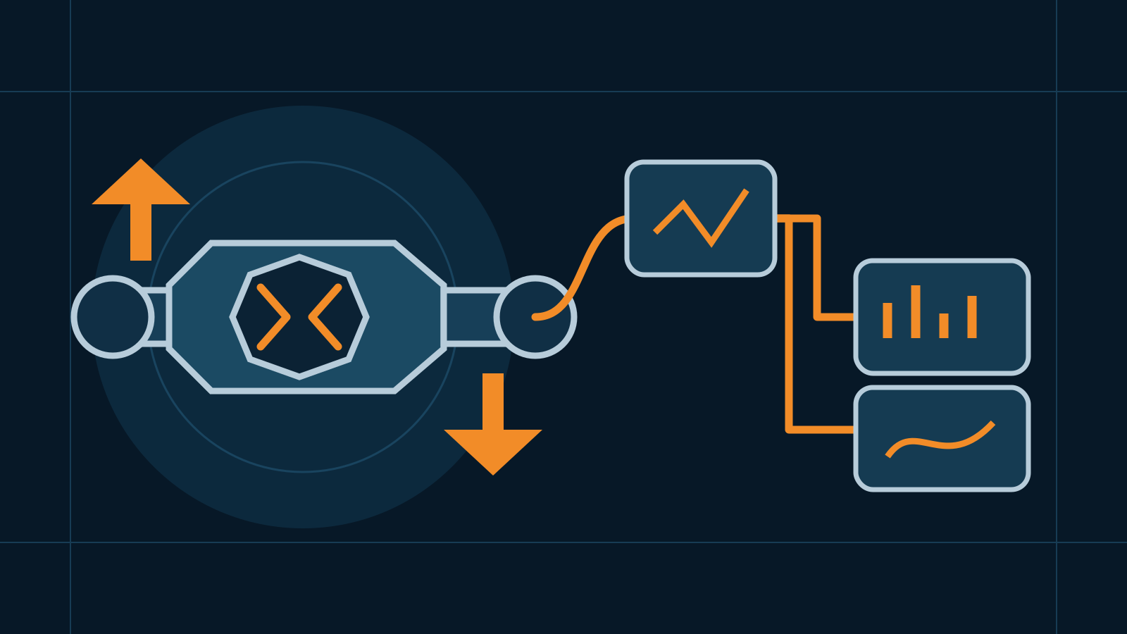
A force transducer converts applied force into an electrical or digital signal that can be displayed, recorded, or used by a control system. Selecting one requires more than choosing a force range: the loading direction, fixtures, side loads, environment, signal conditioning, data acquisition, calibration, and safety of the complete installation all affect whether the measurement is useful.
Key takeaways
- “Force transducer” is a broad term; a load cell is one common kind of force transducer.
- A dynamometer is usually a complete force-measuring instrument, not merely the sensing element.
- The complete force measurement system includes mechanics, cables, electronics, software, calibration, and the transducer itself.
- No sensor technology or package is universally best. Choose around the load path, measurement objective, environment, and risk.
- Installed-system calibration is more informative than relying only on a component data sheet.
How a force transducer works
A transducer responds to force through a predictable physical change and turns that change into a usable signal. In a common strain-gauge design, force elastically deforms a machined element. Bonded gauges change electrical resistance, and a bridge circuit produces an output related to the applied force. Other force-sensing approaches may use piezoelectric, hydraulic, pneumatic, optical, or other principles.
Those technologies do not behave identically. A strain-gauge device can suit many static and changing measurements. Some piezoelectric systems are especially useful for dynamic events but require compatible charge or voltage electronics and may not be appropriate for every long-duration static measurement. Hydraulic or pneumatic designs may be chosen for particular environments or indication methods. Product documentation should establish the actual behavior rather than a general category label.
Force transducer vs load cell vs dynamometer
The three terms overlap in everyday use, but they describe different scopes.
| Term | Practical meaning | Typical boundary |
|---|---|---|
| Force transducer | A device that converts force into a measurable output | Broad category; may use different sensing principles and packages |
| Load cell | A force transducer commonly designed for weighing or a defined force-measurement load path | Often strain-gauge based, but specifications and use still vary by model |
| Dynamometer | An instrument or assembly for measuring force, tension, or torque | Commonly combines a sensor with loading hardware, electronics, display, and functions such as peak capture |
A load cell can therefore be a force transducer, and a dynamometer can contain a load cell or another transducer. The names alone do not prove accuracy, safety rating, calibration status, or suitability. For suspended-force applications, the distinction between the instrument and its intended workflow is explored further in crane scale versus dynamometer.
The complete force measurement system
The transducer is only one part of the measurement chain. A complete force measurement system assembled around a sensor commonly includes:
- Mechanical interfaces: adapters, rods, platens, bearings, fixtures, frames, restraints, and alignment features that carry force into the intended sensing axis.
- Transducer: the elastic or responsive element, housing, connector, and any integrated electronics.
- Excitation and signal conditioning: bridge supply, amplifier, filtering, linearization, isolation, or conversion as required by the device.
- Cable and connections: wiring that preserves signal integrity and environmental sealing without imposing unwanted mechanical loads.
- Indication or data acquisition: a display, controller, recorder, or acquisition interface with suitable input range and sampling behavior.
- Configuration and software: scaling, units, zero, filters, peak detection, alarms, logging, and access controls.
- Calibration and records: a documented relationship between known applied force and system indication, with relevant setup and environmental details.
“Secondary” does not mean unimportant. It generally distinguishes a working or transfer measurement chain from the reference system used to establish its response. The exact metrological role depends on the application and calibration hierarchy. Avoid assuming that a transducer plus a generic display automatically forms a traceable or fit-for-purpose system.
Common force transducer configurations
Compression sensors
Compression transducers measure pushing force through specified loading surfaces. Canister, pancake, and compact button forms address different space and structural needs. Their mounts may require flat contact, a loading cap, spherical alignment, or an engineered module. The compression load cell guide explains why those packages are not interchangeable.
Tension and bidirectional sensors
Tension devices measure pulling force through threaded ends, rod ends, pins, shackles, or other rated interfaces. Some pancake, S-shaped, and inline sensors measure both tension and compression, but fixtures must be appropriate for each direction and any reversal. Threads and adapters are part of the load path and require the same specification discipline as the transducer.
Reaction and inline arrangements
A reaction sensor is commonly installed against a structure so force reacts through its body, while an inline sensor sits directly in a tensile or compressive path. Either arrangement can work when it matches the product design. Structural stiffness, parasitic load, alignment, and fixture deformation can influence results in both.
Dynamic force measurement
Impact, forming, vibration, and short-duration tests introduce additional questions: transducer stiffness, natural behavior, amplifier bandwidth, sampling, filtering, mounting resonance, peak capture, and cable effects. There is no universally correct sample rate or filter. The event duration and measurement objective should drive the design, with advice from the sensor and acquisition-system manufacturers.
Selection table
| Question | What to define before purchase |
|---|---|
| What force must be measured? | Direction, working range, preload, peaks, reversals, and credible overloads |
| What result is needed? | Trend, control input, pass/fail point, peak, test curve, or calibrated reported value |
| How will force enter the sensor? | Contact surface, threads, adapters, alignment, frame stiffness, and possible side loads |
| What surrounds the sensor? | Temperature, moisture, chemicals, washdown, vibration, electrical noise, and hazardous conditions |
| What output is usable? | Bridge-level, amplified analog, frequency, or digital output compatible with the receiving instrument |
| How fast must the system respond? | Event duration, useful bandwidth, acquisition behavior, filtering, and synchronization |
| How will it be maintained? | Inspection access, connector and cable protection, recalibration path, spares, and records |
Capacity selection should include all forces the transducer will experience, not just the nominal process target. At the same time, excessive range can make small changes harder to resolve. A qualified engineer or supplier can help balance normal operation, abnormal loading, structural limits, and desired measurement performance without treating a nominal overload specification as permission for routine misuse.
Installation errors that distort results
Force should pass through the intended axis and interfaces. Misalignment, bending, torque, side load, uneven contact, loose adapters, fixture friction, cable pull, temperature gradients, or a flexible frame can change the indication or damage the assembly. A well-specified sensor cannot correct a poor load path by itself.
Use the manufacturer’s current drawing and instructions for orientation, mating surfaces, threads, torque, support, connectors, and environmental sealing. Do not improvise adapters or modify the sensing body. Where the transducer carries a safety-critical load, have the complete mechanical assembly reviewed for all applicable load cases independently of its measurement function.
Calibration, verification, and uncertainty
Calibration applies known forces and documents how the system responds. Depending on the task, the setup may evaluate multiple points, increasing and decreasing force, zero return, repeatability, reversals, or dynamic response. The chosen reference, fixturing, alignment, environmental conditions, indicator settings, and data processing should be recorded because they can affect the result.
Verification then compares performance with defined acceptance criteria. Those criteria are not universal: a production monitor, research fixture, proof-testing instrument, and regulated weighing system serve different decisions. Recalibration timing should reflect stability history, use, environment, risk, contractual requirements, and manufacturer guidance rather than an unsupported calendar rule.
Safety and procurement checklist
- Define the primary load path separately from the measurement requirement.
- Confirm every sensor, adapter, fastener, fixture, and structure is suitable for its mechanical role.
- Plan safe isolation and support before installation or removal.
- Keep personnel away from tensioned, suspended, or compressed assemblies during tests.
- Protect cables without letting them restrain the sensor.
- Purchase compatible electronics and connectors, not just the transducer.
- Commission and calibrate the assembled measurement chain.
- Document configuration, results, limitations, and return-to-service approval.
This is general selection guidance. Force systems used in lifting, machine protection, product acceptance, or regulated measurement require application-specific engineering and competent installation. Follow manufacturer instructions and consult qualified calibration providers or relevant authorities where applicable.
Frequently asked questions
What does a force transducer measure?
A force transducer converts an applied tensile, compressive, or bidirectional force into a usable output. The supported force direction, range, and output depend on the specific design.
Is a force transducer the same as a load cell?
The terms overlap. A load cell is a force transducer commonly optimized for weighing or force measurement through a defined load path. Force transducer is a broader term that can include several sensing technologies and application-specific packages.
Is a force transducer a dynamometer?
Not by itself. A transducer is the sensing element, while a dynamometer is generally a complete instrument for measuring force, tension, or torque and may incorporate a transducer, electronics, display, and application-specific hardware.
What is included in a force measurement system?
A typical system includes the transducer, mechanical fixtures, cable, excitation and signal conditioning, display or data acquisition, configuration, calibration, and records. Some products integrate several of these functions.
Related guides

Wireless Load Cells: Selection, Radio, Power, and Security
Understand wireless load cell architecture, radio reliability, battery planning, cybersecurity, calibration, and selection without relying on range claims.
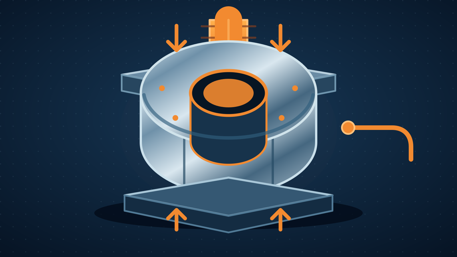
Donut Load Cells: Through-Hole Design and Installation
Learn how a donut load cell, also called a through-hole load cell, measures compression or tension and what reliable, qualified installation requires.
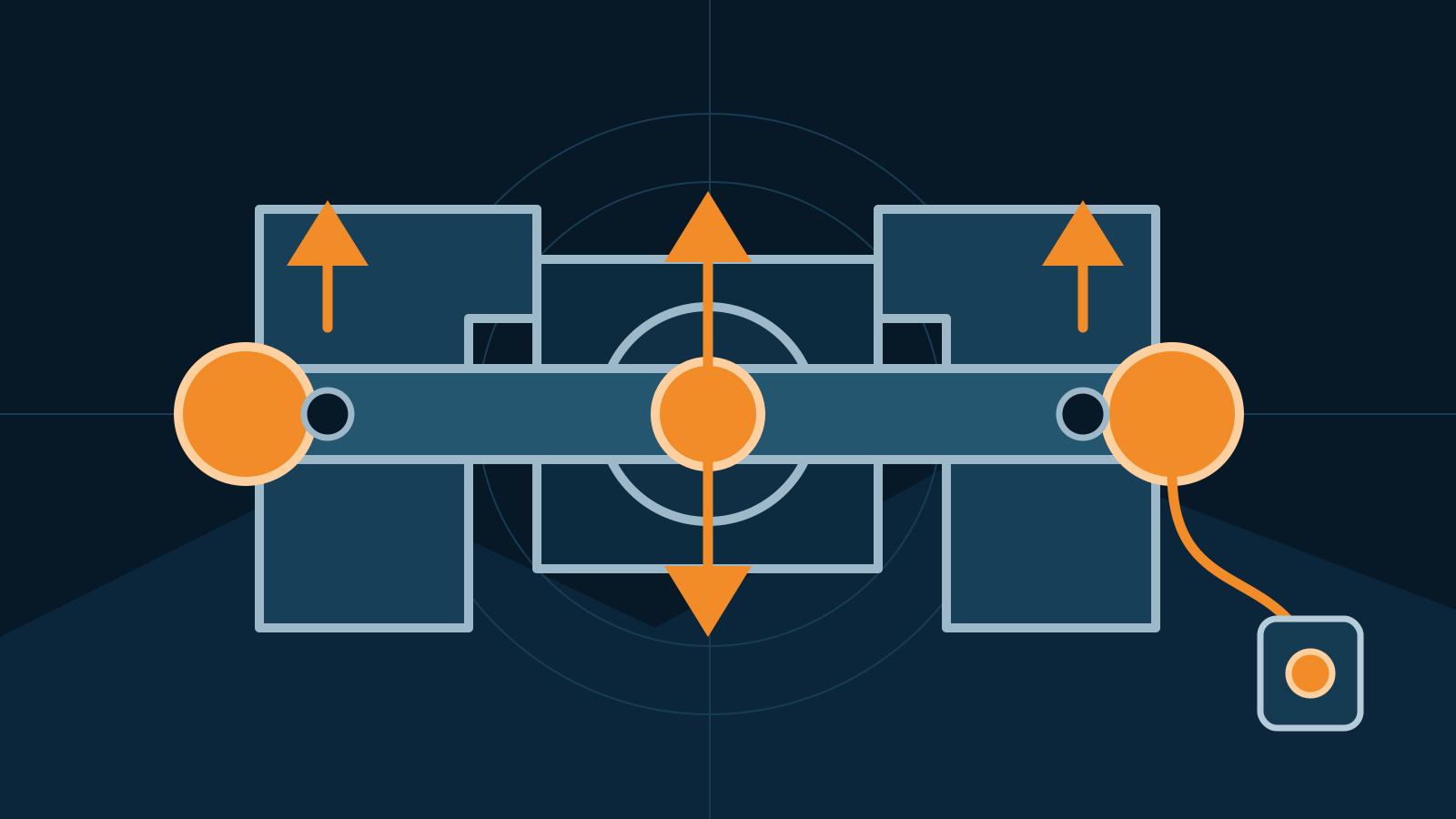
Load Pin: Operation, Selection, Installation, and Safety
Learn how a load pin measures force in clevis and pinned joints, what affects accuracy, and how to specify, install, calibrate, and inspect one safely.