Compression Load Cell: Types, Selection, and Installation
Learn how compression load cells work, compare canister, pancake, and button designs, and review selection, mounting, calibration, and safety factors.
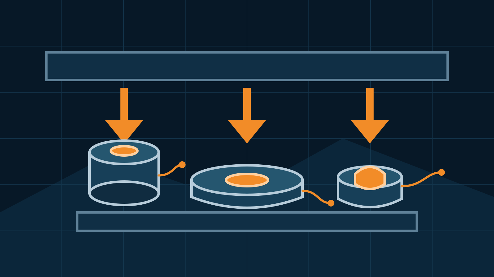
A compression load cell measures a pushing force applied through its intended loading surfaces. It can be part of a tank scale, materials test machine, press monitor, hopper, or other force measurement system, but the right design and mounting arrangement depend on the actual load path. Canister, pancake, and button cells are not interchangeable simply because all three measure compression.
Key takeaways
- Compression cells measure force in a pushing direction; some designs can also measure tension.
- Canister, pancake, and button describe different mechanical packages and application strengths.
- Capacity is only one selection factor. Load introduction, side load, space, environment, output, and the complete measurement chain also matter.
- There is no universal mounting detail. Use the manufacturer’s approved loading hardware and installation drawing for the selected model.
- Calibration should evaluate the assembled system in the conditions that matter to the process.
How a compression load cell works
Most industrial compression load cells use a metal elastic element fitted with strain gauges. Applied force produces a very small, repeatable deformation. The gauges change resistance, and a bridge circuit converts that change into a low-level electrical output. Signal conditioning and an indicator, controller, or data-acquisition system then convert the output into force, mass, or a process value.
The sensing principle may be similar across products, but the housing, elastic element, sealing, loading surfaces, and output format can differ substantially. Some units provide an analog bridge output; others integrate amplification or digital electronics. A useful specification review therefore covers both the mechanical sensor and the electronics receiving its signal.
Canister vs pancake vs button load cells
The best type is the one whose rated loading method and physical geometry fit the structure. The labels below are useful categories, not guarantees of a particular capacity, accuracy, or environmental rating.
| Type | Typical physical form | Common strengths | Points to check |
|---|---|---|---|
| Canister | Cylindrical body with a central loading area | Robust process weighing, tank or hopper supports, test frames | Load introduction hardware, rotation control, lateral forces, mount details, sealing |
| Pancake | Wide, low-profile disc, often with central threaded or loaded features | Low height, test machines, presses, applications that may need tension and compression | Whether the model is compression-only or bidirectional, thread alignment, base stiffness, moment sensitivity |
| Button | Small, compact cylindrical sensor with a raised loading surface | Tight spaces, fixtures, localized force checks | Concentrated loading, support surface, cable protection, allowable side load, installation repeatability |
Canister load cells
Canister-style cells are frequently used where loads are introduced through a substantial cylindrical sensor. Depending on the product, they may be paired with engineered mounting assemblies that accommodate limited movement while controlling uplift or lateral displacement. That can make them suitable for vessels and structures, but only when the mount is designed for the forces and motions present.
A bare canister is not automatically a complete vessel mount. Thermal expansion, piping forces, wind, agitation, restraints, and uneven support conditions can all redirect force. For process weighing, the entire vessel installation matters; our guide to a tank weighing system explains that broader context.
Pancake load cells
A pancake cell uses a broad, shallow body where vertical clearance is limited or a stiff test assembly is desirable. Some models measure compression only, while others are designed for tension and compression through specified threaded or loading interfaces. Pancake geometry can work well in presses and materials-testing frames, provided the fixtures keep the force aligned with the sensing axis.
Do not assume that a low profile makes a sensor insensitive to moments or side loads. Plate flatness, bolt pattern, torque, fixture stiffness, thread engagement, and the location of force introduction may affect results. The product drawing and installation instructions define the required arrangement.
Button load cells
Button or miniature compression cells fit compact fixtures, equipment monitoring points, and development rigs. Their small loading area can be useful where space is scarce, but it also makes surface condition and force introduction important. A hardened loading accessory may be specified to keep contact centered and avoid damaging the sensing surface.
A button cell should not be placed casually between two parts and treated as a universal force washer. Check whether the body requires full support, whether the top is intended for flat or spherical contact, how the cable exits, and how the assembly prevents lateral movement.
Compression load cell selection checklist
Before comparing models, define what the system must measure and what can happen around the intended measurement range.
- Force range and loading profile: Include dead load, operating force, preload, startup effects, impacts, and credible abnormal conditions.
- Required measurement performance: Define useful resolution, repeatability, uncertainty, and response needs for the actual decision being made.
- Load direction: Confirm compression-only or tension-and-compression operation, and identify side loads, bending moments, or rotation.
- Available geometry: Review overall height, loading diameter, mounting features, cable clearance, and access for installation.
- Environment: Consider temperature, moisture, washdown, corrosion, chemicals, vibration, dust, and electrical interference.
- Electrical compatibility: Match excitation, rated output, wiring, amplifier or indicator input, and any digital interface.
- Approvals and documentation: Identify legal-for-trade, hazardous-area, hygienic, machine-safety, or quality-system requirements where applicable.
- Serviceability: Plan protection, inspection access, cable replacement policy, calibration, and safe removal.
Select capacity with engineering margin based on the equipment maker’s guidance and a credible load analysis. Choosing a very high capacity “to be safe” can reduce usable sensitivity, while choosing too close to the normal load can leave inadequate protection against transient or off-axis forces.
Mounting is application-specific
There is no single correct compression load cell mounting procedure. One design may require a flat rigid base and a loading button; another may require a rocker column, spherical accessory, threaded adapter, or complete vessel module. Mixing details between sensor families can introduce side load, point contact, bending, looseness, or an unsafe load path.
Qualified installers should follow the current drawings for the sensor, mount, and host machine. As general review points, confirm that mating surfaces are suitable, force enters through the intended area, the cell is correctly oriented, attachments use specified hardware, cables are protected, and nothing bypasses or binds the measured load path. Do not machine, weld, grind, or alter a sensor or mount unless the manufacturer explicitly authorizes it.
For an existing scale, symptoms such as drift or inconsistent readings should be diagnosed before ordering hardware. Mechanical interference and wiring faults can imitate sensor failure; see the structured load cell troubleshooting process.
Calibration and commissioning
Calibration concerns the whole measurement chain, not the sensor label alone. After installation, inspect the mechanical arrangement and wiring, allow any required stabilization, set up the instrument, and apply suitable reference forces or loads through the normal path. The test plan may include zero return, repeatability, increasing and decreasing points, position effects, or comparison with a reference instrument, depending on the application.
Record the sensor identity, signal conditioner and display settings, reference equipment, loading setup, environmental conditions, as-found data, adjustments, and as-left results. A press-monitoring system used for process trending does not necessarily need the same procedure as a commercial scale or laboratory force machine. Acceptance criteria, intervals, and traceability should come from the application’s risk, quality requirements, jurisdiction, and manufacturer recommendations.
Safety considerations
A compression cell may support a heavy structure or sit inside machinery with stored energy. Isolate the equipment and use an engineered support method before loosening load-bearing parts. Never rely on the measuring sensor, a hydraulic system, or an unsupported lifting device as the sole protection for personnel. Guard pinch points and keep people clear during loading.
This article is general guidance, not a mounting design or safe-work procedure. Have qualified personnel assess the structure, load cases, controls, installation, and return to service. Calibration and any regulated verification should be performed by competent providers under the requirements that apply to the site.
Frequently asked questions
What is a compression load cell?
A compression load cell is a transducer designed to measure force applied in a pushing direction. Its sensing element converts small elastic deformation into an electrical signal that a compatible instrument conditions, displays, or records.
What is the difference between canister, pancake, and button load cells?
Canister cells are robust cylindrical units commonly used for larger structures and process weighing; pancake cells are low-profile sensors that may measure compression alone or both tension and compression; button cells are compact compression sensors for restricted spaces. Exact capabilities depend on the model.
Can any compression load cell be mounted under a tank or press?
No. The cell, mounting hardware, load introduction, restraints, environmental protection, output, and capacity must suit the complete application. Follow the cell and equipment manufacturers' drawings rather than applying one mounting method universally.
Does a compression load cell need calibration after installation?
The complete measurement chain should be calibrated or verified as required for its use after installation. Structural alignment, mounting, cables, signal conditioning, and the indicator can all influence the installed result.
Related guides

Wireless Load Cells: Selection, Radio, Power, and Security
Understand wireless load cell architecture, radio reliability, battery planning, cybersecurity, calibration, and selection without relying on range claims.
Donut Load Cells: Through-Hole Design and Installation
Learn how a donut load cell, also called a through-hole load cell, measures compression or tension and what reliable, qualified installation requires.
Load Pin: Operation, Selection, Installation, and Safety
Learn how a load pin measures force in clevis and pinned joints, what affects accuracy, and how to specify, install, calibrate, and inspect one safely.